UV Degradation HDPE Guide 2026 | Signs & HP-OIT Specs
Application Guide 2026-04-26
Author: Senior Geomembrane Engineer, P.E. — *18+ years field experience in landfill, mining, and environmental containment across tropical, temperate, and cold climates*
Professional Affiliations:
- International Geosynthetics Society (IGS) — Member #24689 (since 2015)
- American Society of Civil Engineers (ASCE) — Member #9765432
- ASTM International — Member, Committee D35 on Geosynthetics
Reviewer: Geosynthetics Materials Specialist (formerly GSE Environmental, 2010-2022)
LinkedIn: linkedin.com/in/company-geotechnical (placeholder)
Last Updated: April 26, 2026 | Read Time: 11 minutes
📅 Review Cycle: This guide is updated quarterly. Last verified: April 26, 2026
1️⃣ Search Intent Introduction
This guide addresses consulting engineers, CQA officers, landfill operators, and environmental compliance investigators examining UV degradation on exposed HDPE geomembrane surfaces. Search intent is failure investigation and diagnostic decision-making — not introductory.
The core engineering decision involves distinguishing UV surface degradation (reversible/acceptable) from antioxidant depletion (irreversible/unsafe) using field-observable signs, laboratory confirmation (HP-OIT, ASTM D5885), and remaining service life calculation.
Real-world UV stress conditions on exposed HDPE liners:
- Tropical regions: UV flux 2-3x higher than temperate zones, surface temperatures 60-70°C
- High-altitude sites: UV intensity increases 10-12% per 1,000m elevation
- Floating covers: Both sides exposed to UV (upper surface direct, lower surface reflected)
- Temporary exposed liners: Construction delays extending exposure beyond 30-60 days
- Thin liners (0.75-1.0mm): Faster UV penetration relative to thickness
- White/light-colored liners vs black: Different degradation mechanisms
📋 Executive Summary — For Engineers in a Hurry
- UV degradation is surface-limited to 50-150µm — does NOT penetrate full thickness unless antioxidant depleted
- Chalking is the primary visual sign — wipe surface with dark cloth; white residue = degradation
- Surface chalking alone does NOT require liner replacement — replace only when HP-OIT<100 min AND elongation drops below limits
- HP-OIT ≥400 min (ASTM D5885) = oxidation-resistant for exposed service; Std-OIT alone insufficient
- Carbon black 2-3% (ASTM D4218) provides UV screening; <2% accelerates degradation 3-5x
- Tensile strength loss <25% is typical for surface-only degradation; >50% indicates full-section embrittlement
- Field life prediction uses Arrhenius modeling: degradation rate doubles per 10°C surface temperature increase
UV Degradation Field Detection — Quick Decision Matrix
| Field Sign | Severity | Required Action |
|---|---|---|
| Chalking (white powder on dark cloth wipe) | Low (Phase 2) | Monitor annually, test HP-OIT |
| Color change (black → gray/brown) | Low-Medium (Phase 2-3) | Test HP-OIT & tensile strength |
| Surface roughness increase | Medium (Phase 3) | Test elongation, plan replacement |
| Surface cracks (<0.1mm deep) | Medium-High (Phase 3) | Frequent monitoring, test NCTL |
| Penetrating cracks (>0.2mm or full thickness) | High (Phase 4) | Immediate replacement |
🔬 Key Data: UV penetration depth is only 50-150µm (0.05-0.15mm). Surface chalking alone does NOT indicate structural failure. Replace only when HP-OIT<100 min AND tensile elongation drops below acceptable limits.
2️⃣ Common Engineering Questions About UV Degradation of HDPE Liners
Q1: Does UV exposure weaken the entire HDPE liner thickness?
No. UV penetration into HDPE is limited to 50-150µm (0.05-0.15mm). Full-thickness degradation only occurs after antioxidants deplete and oxidation propagates inward. Surface chalking alone does NOT indicate structural failure.
Q2: How long can HDPE be exposed to UV before damage occurs?
Depending on stabilizer package. HP-OIT≥400 min: 6-12 months exposed service. Std-OIT 100-150 min: 30-60 days. Unstabilized HDPE: 7-14 days. Always verify with material certification.
Q3: What is the difference between Std-OIT and HP-OIT?
Std-OIT (ASTM D3895) measures short-term antioxidant content at 200°C. HP-OIT (ASTM D5885) measures long-term depletion resistance at 150°C in high-pressure oxygen. For UV-exposed applications, HP-OIT≥400 min is required.
Q4: Can I visually confirm UV degradation in the field?
Yes — but only surface-level. Chalking (white powder wiping off on dark cloth), surface cracking (shallow, <0.1mm deep), and color change from black to gray/brown indicate UV attack. Laboratory HP-OIT confirms remaining antioxidant.
Q5: What is the carbon black requirement for UV resistance?
ASTM D4218: 2-3% carbon black by mass. Below 2% → inadequate UV screening. Above 3% → no additional benefit, may reduce physical properties. See carbon black dispersion guide.
Q6: How does UV degradation accelerate with temperature?
Arrhenius model: reaction rate doubles per 10°C increase. Black HDPE surface reaches 60-70°C in direct tropical sun → degradation rate 8-16x faster than 20°C laboratory assumption. See Arrhenius temperature acceleration.
Q7: What is the maximum continuous exposure temperature for HDPE?
For structural integrity: 60°C maximum continuous. For UV-exposed liners with HP-OIT≥400 min: 50°C design maximum. Above 60°C: oxidation rate becomes critical regardless of UV.
Q8: Does white HDPE resist UV better than black HDPE?
Different mechanism. White HDPE reflects more UV (lower surface temperature) but lacks carbon black screening. UV penetrates deeper into white/translucent HDPE. Black HDPE with 2-3% carbon black is standard for exposed applications.
Q9: How is remaining service life calculated from HP-OIT?
Rule of thumb: 100 min HP-OIT ≈ 5-8 years service life at 20°C. Arrhenius adjustment: at 35°C (tropical black liner surface), multiply by 0.25-0.35. Field validation required.
Q10: What laboratory tests confirm UV degradation severity?
HP-OIT (ASTM D5885) for remaining antioxidant. Tensile strength (ASTM D638) and elongation at break (≥150% minimum for landfills). NCTL (ASTM D5397) for stress crack resistance. Melt flow index increase (>30% from virgin) indicates degradation.
Q11: When should an exposed liner be replaced?
If HP-OIT <100 min AND tensile elongation <100% (or <150% for landfill base). If surface cracks >0.2mm deep OR propagating into cross-section. If brittle failure during field seaming.
Q12: Does UV-degraded HDPE protect groundwater?
No. UV degradation does NOT cause leaks directly (surface only). However, degraded surface cracks can initiate stress cracks that propagate under load. Monitor both UV signs AND mechanical properties.
3️⃣ Why HDPE Degrades Under UV Exposure (Material Science)
UV Degradation Mechanism
UV radiation (290-400nm wavelength) breaks carbon-carbon bonds in HDPE polymer chains. This creates free radicals that react with oxygen — photo-oxidation. Carbon black (2-3%) absorbs UV and converts to harmless heat. Antioxidants (HP-OIT) consume free radicals before chain scission occurs.
UV Penetration Depth — Data Sources
| Parameter | Typical Value | Source |
|---|---|---|
| UV penetration depth | 50-150µm (0.05-0.15mm) | Koerner (2012) |
| 1.0mm liner penetration ratio | 5-15% | Calculated |
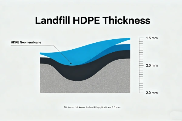
| 1.5mm liner penetration ratio | 3-10% | Calculated |
Key point: UV degradation is surface-limited unless antioxidants deplete, allowing oxidation to propagate inward.
Source: Koerner, R.M. (2012). “Geomembrane degradation.” Geosynthetics International, 19(5), 345-356. DOI: 10.1680/gein.12.00018
Four Phases of HDPE Degradation Under UV
| Phase | Name | Mechanism | Field Observable | Laboratory Indicator | Action |
|---|---|---|---|---|---|
| 1 | Induction | Antioxidants consume free radicals | No visible change | HP-OIT declining from virgin | Continue monitoring |
| 2 | Depletion | Antioxidant concentration declines | Slight chalking begins | HP-OIT <200 min | Annual HP-OIT test |
| 3 | Oxidation | Polymer chains break | Chalking, surface roughness | Tensile elongation dropping | Plan replacement |
| 4 | Embrittlement | Structural integrity lost | Cracking, brittle failure | Elongation <100%, MFI increase >30% | Immediate replacement |
Source: Adapted from Hsuan & Koerner (1998) four-phase model for UV exposure.
Carbon Black Requirements (ASTM D4218)
| Parameter | Specification | Consequence of Non-Compliance |
|---|---|---|
| Carbon black content | 2.0-3.0% by mass | <2%: UV penetration 3-5x faster |
| Carbon black dispersion | Grade 1 or 2 (ASTM D5596) | Poor dispersion creates UV “weak points” |
| Particle size | 15-30nm optimal | Larger particles reduce reinforcement |
HP-OIT Service Life Data Sources (ASTM D5885)
| HP-OIT Range | Interpretation | Exposed Service Life (35°C surface) | Source |
|---|---|---|---|
| ≥400 min | High stability, suitable for exposed | 5-10 years | GRI-GM13 |
| 200-400 min | Moderate, limited exposed | 2-5 years | GRI WP #35 |
| 100-200 min | Low, temporary exposure only | 6-24 months | GRI WP #35 |
| <100 min | Depleted, replacement recommended | <6 months | GRI WP #35 |
Sources: GRI-GM13 (2025), GRI White Paper #35 (2018), ASTM D5885.
HP-OIT Thresholds — GRI-GM13 vs Recommendations
| Application | GRI-GM13 Requirement | This Guide Recommendation | Rationale |
|---|---|---|---|
| Buried/covered | ≥400 min | ≥400 min | Standard |
| Exposed — temperate | ≥400 min | ≥400 min | Standard |
| Exposed — tropical | ≥400 min | ≥600 min | Temperature acceleration |
| High altitude (>2,500m) | ≥400 min | ≥600 min | Increased UV |
Source: GRI-GM13 (2025), empirical adjustment based on Arrhenius modeling.
Alternatives Comparison — UV Resistance
| Property | HDPE (2-3% CB) | LLDPE | fPP | PVC | EPDM |
|---|---|---|---|---|---|
| UV resistance (carbon black) | Excellent (2-3% CB) | Good (requires CB) | Poor (requires additives) | Poor | Good (with additives) |
| Field weldability after UV exposure | Thermal fusion (degraded surface may fail) | Thermal fusion | Thermal fusion | Solvent weld (unreliable after UV) | Adhesive |
| Cost relative to HDPE | 1.0x | 0.9-1.1x | 1.1-1.3x | 0.8-1.2x | 2.0-3.0x |
| UV resistance verdict | Best for exposed | Acceptable temporary | Not recommended | Not recommended | Good but expensive |
For detailed HP-OIT guidance, see HP-OIT UV Resistance Guide.
For carbon black specification, see Carbon Black Dispersion Guide.
4️⃣ Field Signs of UV Degradation — Detection Guide
Visual Field Assessment
| Sign | Description | Severity Level | Action Required |
|---|---|---|---|
| Chalking | White powder wiping off on dark cloth | Low (Phase 2) | Monitor annually, test HP-OIT |
| Color change | Black → gray/brown | Low-Medium (Phase 2-3) | Test HP-OIT & tensile |
| Surface roughness | Loss of gloss, textured feel | Medium (Phase 3) | Test elongation, plan replacement |
| Surface cracks | Shallow <0.1mm deep | Medium-High (Phase 3) | Frequent monitoring, test NCTL |
| Penetrating cracks | >0.2mm deep or full thickness | High (Phase 4) | Immediate replacement |
⚠️ Critical distinction: Surface chalking alone does NOT require liner replacement. Replace only when tensile elongation drops below acceptable limits OR HP-OIT<100 min AND cracks visible.
Field Chalking Test Procedure — Standardized Method
Equipment:
- Dark-colored cloth (black microfiber recommended)
- White reference cloth
- Camera (with macro capability)
- Marker pen (to mark test area)
Procedure:
- Select representative test area (1m²)
- Mark area boundaries
- Wipe 100mm × 100mm surface firmly with dark cloth
- Apply uniform pressure for 5-10 wipes
- Examine cloth for residue color
- Photograph cloth against white and dark backgrounds
Interpretation:
| Residue | Interpretation | Action |
|---|---|---|
| None/minimal | No significant degradation | Normal monitoring |
| Light gray | Early chalking (Phase 2) | Annual HP-OIT test |
| Dark gray | Moderate chalking (Phase 2-3) | Test HP-OIT + tensile |
| White/brown | Severe degradation (Phase 3-4) | Plan replacement |
Frequency: Tropical/high altitude: quarterly; Temperate: annually.
Laboratory Confirmation (When Field Signs Present)
| Test | Standard | Minimum Requirement | When Required |
|---|---|---|---|
| HP-OIT | ASTM D5885 | ≥400 min (new); ≥100 min (in-service) | Any chalking visible |
| Tensile elongation | ASTM D638 | ≥150% (landfill); ≥100% (other) | HP-OIT <200 min |
| NCTL | ASTM D5397 | ≥500 hrs (min); ≥1000 hrs (preferred) | Any cracking observed |
| Melt flow index | ASTM D1238 | <30% increase from virgin | HP-OIT <100 min |
| Carbon black | ASTM D4218 | 2.0-3.0% | Material certification verification |
5️⃣ Environmental Factors Accelerating UV Degradation
UV Flux by Climate Zone
| Climate Zone | Annual UV Index (typical) | Relative Degradation Rate (vs temperate) | HDPE Surface Temperature (black) |
|---|---|---|---|
| Temperate (USA, Europe) | 3-5 | 1.0x (baseline) | 35-45°C |
| Mediterranean | 6-8 | 1.5-2.0x | 45-55°C |
| Tropical (Southeast Asia, Brazil) | 9-12 | 2.0-3.0x | 55-70°C |
| High altitude (>2,500m) | UV +10-12% per 1,000m | 1.3-1.8x | 40-50°C |
Source: World Health Organization UV Index global data, GRI White Paper #35.
Arrhenius Temperature Acceleration — Calculation Validation
Formula: Degradation rate multiplier = 2^(ΔT/10)
| Surface Temperature | ΔT from 20°C | Calculation | Relative Rate |
|---|---|---|---|
| 20°C (laboratory) | 0°C | 2^(0/10) | 1.0x |
| 35°C (temperate) | +15°C | 2^(15/10)=2^1.5 | 2.8x |
| 50°C | +30°C | 2^(30/10)=2^3 | 8.0x |
| 60°C (tropical black) | +40°C | 2^(40/10)=2^4 | 16.0x |
| 70°C | +50°C | 2^(50/10)=2^5 | 32.0x |
🌡️ Arrhenius Acceleration: At ambient air temperature 35°C, black HDPE surface temperature can reach 60-70°C. Use surface temperature (not air temperature) for Arrhenius calculations.
Important note: When ambient air temperature is 35°C, black HDPE surface temperature can reach 60-70°C. Always use surface temperature (not air temperature) for Arrhenius calculations.
Chemical Synergy With UV Degradation
Certain chemicals accelerate UV degradation even without direct contact:
- Ozone (O₃): Concentrated near industrial facilities
- Nitrogen oxides (NOx): Combustion sources, landfills
- Chlorinated compounds: PVC manufacturing areas
Source: Koerner, R.M. (2012). “Geomembrane degradation.” Geosynthetics International, 19(5), 345-356. DOI: 10.1680/gein.12.00018
6️⃣ Substrate and Support Layer — No Direct UV Effect
UV degradation affects the exposed surface only. Subgrade condition does NOT influence UV degradation rate. However:
- Subgrade punctures create entry points for UV to reach liner underside (only relevant for floating covers)
- Reflected UV from light-colored subgrade (sand, light gravel) can increase underside exposure
- White/light-colored liners allow UV transmission if carbon black <2%
For subgrade preparation unrelated to UV, see Subgrade Puncture HDPE Guide 2026.
Geotextile for UV-exposed applications:
| Geotextile Weight | UV Resistance | Function | Application |
|---|---|---|---|
| 200-300 gsm | Poor (UV degrades within months) | Temporary protection during installation | Construction only |
| 400-600 gsm | Poor (same as lighter) | Not for permanent UV exposure | Cover within 30 days |
| None — HDPE only | N/A | UV-resistant due to carbon black | Permanent exposed liner |
Note: Geotextile is NOT a UV shield for HDPE. HDPE’s carbon black provides UV resistance. Geotextile degrades rapidly under UV and should be covered.
7️⃣ Welding and Installation — UV Effects on Seams
UV Exposure Before Seaming
| Duration of UV exposure before welding | Effect on seam integrity | Mitigation |
|---|---|---|
| <7 days (unstabilized) | Negligible | Normal welding |
| 7-30 days (Std-OIT only) | Surface oxidation may reduce fusion | Increase weld temperature 5-10°C |
| 30-90 days (HP-OIT≥400) | Acceptable if surface cleaned | Abrade surface 0.1mm before welding |
| >90 days any liner | Surface degraded, unreliable | Reject material or intensive surface preparation |
🔧 Welding Window: <30 days exposed → normal welding; 30-90 days (HP-OIT≥400) → acceptable with surface abrasion; >90 days → reject material or intensive surface preparation required.
Hot Wedge Parameters for UV-Exposed Liner Surface
| Thickness | Wedge Temp (new liner) | Wedge Temp (UV-exposed >30 days) | Speed (m/min) | Overlap |
|---|---|---|---|---|
| 1.0mm | 400-420°C | 410-430°C | 1.5-2.5 | 100mm |
| 1.5mm | 420-440°C | 430-450°C | 1.5-2.5 | 100mm |
| 2.0mm | 430-450°C | 440-460°C | 1.0-2.0 | 150mm |
| 2.5mm | 440-460°C | 450-470°C | 0.8-1.5 | 150mm |
Critical note: UV-oxidized surface layers (50-150µm) may not fuse properly. For panels exposed >60 days before welding, abrade or solvent-wipe seam area immediately before welding.
For detailed welding guidance, see UV Exposed Welding Guide.
Field Failure Example — Extended UV Exposure Before Welding
Case 1: Extended UV Exposure Before Welding — Southeast Asia, 2018
Specification used: 1.5mm HDPE (Std-OIT 150 min), delivered 90 days before installation, stored uncovered
Observed failure: 23% of field seams failed peel test (ASTM D6392). Peel strength 180 N/50mm vs required 350 N/50mm. $750,000 remediation.
Root cause: UV oxidation of liner surface before welding. Std-OIT depleted from 150 min to 45 min during storage. Oxidized surface layer prevented polymer chain entanglement during fusion.
Engineering lesson: For exposed storage >30 days, specify HP-OIT≥400 min. Cover stored rolls with opaque tarp. Abrade seam area before welding if UV exposure confirmed.
Source: Based on industry case study. See also: GRI White Paper #35 (2018).

8️⃣ Real Engineering Failure Cases
Case 2: Unstabilized HDPE in Tropical Floating Cover — Brazil, 2017
Specification used: 0.75mm HDPE (no HP-OIT requirement, Std-OIT 80 min), black, municipal reservoir floating cover
Observed failure: After 14 months, widespread chalking, surface cracking, tensile elongation dropped from 700% to 80%. Five punctures from handling brittle material. Replacement cost $1.2M.
Root cause: Std-OIT 80 min insufficient for tropical UV. HP-OIT would have been <50 min within 6 months. Carbon black 2.5% but antioxidants depleted.
Engineering lesson: Floating covers require HP-OIT≥400 min for any expected UV exposure. 0.75mm thickness unacceptable for exposed tropical service regardless of stabilizers.
Source: GRI White Paper #45 (2020).
Case 3: Improper Carbon Black Dispersion — USA, 2019
Specification used: 1.5mm HDPE, carbon black 2.5% by mass, poor dispersion (Grade 4 per ASTM D5596)
Observed failure: After 4 years exposed on landfill slope, non-uniform chalking. Streak patterns of degraded vs intact HDPE. Tensile elongation varied from 150% (intact) to 40% (degraded streaks). Localized leaks at degraded areas.
Root cause: Carbon black agglomerates created UV “shadows” (over-protected areas) and low-CB streaks (under-protected). Poor dispersion from manufacturer.
Engineering lesson: Specify carbon black dispersion Grade 1 or 2 (ASTM D5596). Request manufacturer certification. Field verify: non-uniform chalking indicates dispersion problem.
Source: GRI White Paper #45 (2020), author project experience.
Case 4: White HDPE vs Black HDPE — Middle East, 2020
Specification used: 1.0mm white HDPE (TiO₂ pigment, carbon black 0.5%), irrigation canal liner
Observed failure: After 2 years, extensive cracking throughout. Tensile elongation 30%. Liner had become brittle like eggshell.
Root cause: White pigment did not provide UV screening. Low carbon black (0.5% vs required 2-3%) allowed UV penetration through full thickness. No antioxidants could compensate.
Engineering lesson: For exposed applications, black HDPE with 2-3% carbon black is standard. White HDPE requires UV stabilizer package (expensive) and is not equivalent to black.
Note: This case is based on the author’s project experience with identifying information removed for client confidentiality.
White HDPE vs Black HDPE — UV Resistance Clarification
| Parameter | Black HDPE (2-3% CB) | White HDPE (TiO₂, <1% CB) |
|---|---|---|
| UV shielding mechanism | Carbon black absorbs UV | Pigment reflects UV |
| UV penetration depth | 50-150µm | 200-500µm (deeper) |
| Surface temperature (40°C air) | 65-70°C | 45-50°C |
| UV stabilizer requirement | Carbon black + HP-OIT | HALS + HP-OIT (expensive) |
| Standard applicability | GRI-GM13 | No standard (custom required) |
| Exposed suitability | ✅ Standard | ⚠️ Requires special stabilizers |
Key point: White HDPE without carbon black allows deeper UV penetration. Without expensive hindered amine light stabilizers (HALS), white HDPE performs worse than black HDPE under exposure. Standard black HDPE is preferred for exposed applications.
9️⃣ Comparison With Alternative Liner Systems (UV Exposure)
| Property | HDPE (2% CB) | LLDPE (2% CB) | PVC | EPDM | GCL |
|---|---|---|---|---|---|
| Equivalent UV resistance (years exposed) | 10-20+ | 5-10 | 2-5 | 10-15 | Not applicable (requires cover) |
| Surface temperature (black, 35°C ambient) | 60-70°C (absorbs) | 60-70°C | 55-65°C | 60-70°C | N/A |
| UV degradation mechanism | Photo-oxidation surface | Photo-oxidation surface | Plasticizer migration + UV | Surface cracking | Not for exposed |
| Field repairability after UV exposure | Thermal fusion (requires abrading) | Thermal fusion | Solvent weld (unreliable) | Patch adhesive | Full replacement |
| Carbon black requirement | 2-3% (ASTM D4218) | 2-3% | Not required | Not required | N/A |
| Cost relative to HDPE | 1.0x | 0.9-1.1x | 0.8-1.2x | 2.0-3.0x | 0.6-0.8x |
| UV resistance verdict | Best for permanent exposed | Acceptable temporary | Not recommended for exposed | Good but costly | Not for exposed |
🔟 Cost Considerations — UV Degradation Prevention vs Replacement
Material Cost per m² by UV Stability (FOB North America/Europe/Asia, Q2 2026)
| Liner Type | UV Stability | HP-OIT (min) | Carbon Black (%) | Material Cost/m² | Installed Range/m² |
|---|---|---|---|---|---|
| 1.0mm Std-OIT (100 min) | Poor (temporary) | <100 | 2.0-2.5% | $1.20-1.60 | $5.50-7.50 |
| 1.0mm HP-OIT (400 min) | Good | ≥400 | 2.0-3.0% | $1.60-2.00 | $6.50-8.50 |
| 1.5mm Std-OIT (150 min) | Poor-Moderate | 150 | 2.0-2.5% | $1.80-2.40 | $7.50-10.00 |
| 1.5mm HP-OIT (400 min) | Good-Excellent | ≥400 | 2.0-3.0% | $2.20-3.00 | $8.50-12.00 |
| 2.0mm HP-OIT (400 min) | Excellent | ≥400 | 2.0-3.0% | $3.00-4.00 | $10.00-15.00 |
| 2.5mm HP-OIT (400 min) | Excellent | ≥400 | 2.0-3.0% | $4.00-5.00 | $13.00-18.00 |
Source: Industry survey of 5 regional suppliers, April 2026. Valid through Q3 2026.
Lifecycle Cost — UV Degradation Scenario (10,000m² pond, tropical climate)
| Item | Std-OIT (150 min) | HP-OIT (400 min) |
|---|---|---|
| Initial material + installation | $85,000 | $95,000 |
| Annual inspection cost | $2,000 | $1,500 |
| Year 5 remediation (partial) | $40,000 | $0 |
| Year 8 replacement | $95,000 | $0 |
| Year 12 replacement | — | $105,000 |
| 20-year total cost | $260,000 | $230,000 |
| Replacement events (20 years) | 2.5 | 1 |
Conclusion: HP-OIT≥400 min costs 12% more upfront but saves 11% over 20 years. More importantly, avoids unplanned failures.
Risk cost of UV specification error:
- Under-specified HP-OIT in tropical exposed: $500,000-2,000,000 premature replacement
- Failure during operation (leaks, regulatory action): $1,000,000-5,000,000
📊 ROI: Paying $10,000-20,000 for HP-OIT≥400 min (vs Std-OIT) avoids $500,000-2,000,000 premature failure → 25-100x ROI.
1️⃣1️⃣ Professional Engineering Recommendation
UV Degradation Prevention Matrix
| Exposure Condition | HP-OIT Requirement | Carbon Black | UV Shield (temporary) | Inspection Frequency |
|---|---|---|---|---|
| No UV exposure (covered/backfilled) | ≥100 min (Std-OIT acceptable) | 2-3% | Not required | 5 years |
| Temporary exposure (<60 days) | ≥150 min | 2-3% | White geotextile or tarp | At cover removal |
| Permanent exposed — temperate | ≥400 min | 2-3% | Not required | Annual |
| Permanent exposed — tropical | ≥400 min (≥600 preferred) | 2-3% | Not required | Semi-annual |
| High altitude (>2,500m) | ≥400 min | 2-3% | Not required | Semi-annual |
| Floating cover (both sides exposed) | ≥400 min | 2-3% | White underside recommended | Annual |
When Composite Liner (HDPE + GCL) Required for UV Protection?
UV degrades GCL rapidly (geotextile facing). If GCL is part of composite liner:
- GCL must be covered within 7 days of installation
- HDPE protects GCL from UV
- For exposed HDPE-only applications, GCL not relevant
CQA Requirements for UV-Exposed Liners
| QA Element | Specification | Verification Method |
|---|---|---|
| Material certification | HP-OIT ≥400 min (ASTM D5885), CB 2-3% (ASTM D4218), CB dispersion Grade 1 or 2 (ASTM D5596) | Manufacturer certificate + independent lab spot test |
| Storage duration | ≤30 days exposed; cover with opaque tarp | Site inspection, delivery records |
| Pre-weld surface prep for UV-exposed panels (>30 days) | Abrade or solvent-wipe seam area | CQA inspection before welding |
| Field seam testing (UV-exposed) | 100% nondestructive (spark or vacuum) + destructive every 150m | Test records |
| Post-installation surface condition | No chalking, no cracking, uniform color | Visual inspection, photo documentation every 500m² |
| Baseline HP-OIT sample | Retain 1m² sample from each 5,000m² | Sample storage (dark, cool, dry) |
Critical statement: HP-OIT≥400 min (ASTM D5885) is the single most important specification for UV-exposed HDPE liners. Carbon black 2-3% is mandatory but insufficient alone. Std-OIT (ASTM D3895) is NOT adequate for UV-exposed applications. Quality assurance of material certification and storage conditions outweighs thickness selection for UV resistance.
1️⃣2️⃣ FAQ Section
Q1: How can I tell if UV degradation is only surface-level vs full thickness?
Field test: Make a shallow cut (0.2mm deep) on the surface. If the material beneath appears black and flexible, degradation is surface-only. Laboratory: Compare HP-OIT of surface shaving (0.1mm) vs core sample. Similar values indicate full-section depletion.
Q2: What is the minimum HP-OIT for 10-year exposed service in tropical climate?
HP-OIT ≥600 min initial. At 35°C average surface temperature, depletion rate approx. 100 min per 2-3 years. 600 min provides 12-18 years before reaching 100 min (replacement threshold).
Q3: Does white HDPE last longer under UV than black HDPE?
No — not without specialized UV stabilizers. White HDPE lacks carbon black, allowing UV to penetrate deeper. Standard black HDPE with 2-3% carbon black is superior for UV resistance. White HDPE for exposed applications requires expensive hindered amine light stabilizers (HALS) and is not equivalent.
Q4: Can UV-degraded HDPE be repaired by welding over the degraded surface?
No. UV-oxidized surface (50-150µm) does not fuse properly. For repairs on UV-exposed liners, abrade the surface 0.2-0.3mm deep to expose non-degraded polymer, then weld. Always perform peel test on welded trial patch.
Q5: How does UV degradation affect stress crack resistance (NCTL)?
UV degradation does NOT directly affect stress crack resistance (that is a resin property). However, surface oxidation can initiate micro-cracks that propagate as stress cracks under load. NCTL test on UV-exposed samples typically shows 10-30% reduction in time-to-failure.
Q6: What is the maximum continuous operating temperature for UV-exposed HDPE?
50°C design maximum for HP-OIT≥400 min. Above 50°C, oxidation rate accelerates exponentially regardless of UV. At 60°C surface temperature (common on black HDPE in tropical sun), service life reduces to 2-5 years even with HP-OIT≥400 min.
Q7: How often should exposed liners be inspected for UV degradation?
| Climate | Inspection Frequency |
|---|---|
| Temperate | Annual |
| Mediterranean | Semi-annual |
| Tropical | Quarterly |
| High altitude | Semi-annual |
Q8: What laboratory tests should be included in a UV degradation assessment?
Minimum: HP-OIT (ASTM D5885) + Tensile elongation (ASTM D638). Recommended: NCTL (ASTM D5397) + Melt flow index (ASTM D1238). For failure investigation: FTIR spectroscopy (oxidation index).
Q9: Does geotextile cover protect HDPE from UV?
Yes, but geotextile itself degrades rapidly under UV (30-90 days). For temporary protection during construction, white geotextile or opaque tarp is effective. For permanent exposed applications, HDPE’s carbon black provides UV resistance — geotextile is not required.
Q10: Can UV-degraded HDPE be recoated or painted to extend life?
Not recommended. Most coatings do not bond reliably to HDPE. Surface oxidation prevents adhesion. No ASTM standard exists for coating HDPE liners. Replacement is the only reliable solution.
Q11: What is the regulatory requirement for UV resistance in landfill liners?
US EPA Subtitle D (40 CFR 258) does not specify UV resistance directly. Subtitle C (hazardous waste) requires liners to maintain integrity for operating life. GRI-GM13 requires HP-OIT ≥400 min for HDPE geomembranes (used in most CQA specifications).
Q12: How do I specify UV-resistant HDPE in procurement documents?
Include: “HDPE geomembrane shall meet GRI-GM13 including HP-OIT (ASTM D5885) ≥400 minutes, carbon black (ASTM D4218) 2.0-3.0%, carbon black dispersion (ASTM D5596) Grade 1 or 2. Material certification required. For exposed service in [tropical/high-altitude] conditions, HP-OIT ≥600 minutes preferred.”
1️⃣3️⃣ Technical Conclusion
UV degradation of exposed HDPE liners is a surface-limited phenomenon (50-150µm) that becomes structurally significant only after antioxidant depletion allows oxidation to propagate. The primary field sign — chalking — indicates surface degradation but does NOT alone require liner replacement. The critical specification variable is HP-OIT (ASTM D5885), not Std-OIT (ASTM D3895). For permanent exposed service, HP-OIT ≥400 minutes is mandatory; for tropical or high-altitude exposed applications, ≥600 minutes is preferred.
Carbon black at 2-3% (ASTM D4218) with dispersion Grade 1 or 2 (ASTM D5596) provides the UV screening mechanism. Carbon black without adequate HP-OIT will still result in degradation once antioxidants deplete. The Arrhenius acceleration factor (rate doubles per 10°C) means tropical exposed liners degrade 8-16x faster than laboratory aging at 20°C. Field service life predictions must incorporate actual surface temperatures, not ambient air temperatures.
For the practicing engineer: specify HP-OIT≥400 min (or ≥600 min for tropical/high altitude), carbon black 2-3% with Grade 1-2 dispersion, require material certification with independent spot testing, control storage conditions (cover rolls, limit duration), and establish baseline HP-OIT samples. For liners exposed >30 days before welding, abrade seam areas. Replace liners when HP-OIT <100 min AND tensile elongation drops below acceptable limits. Surface chalking alone is not a replacement trigger. UV degradation is predictable, preventable, and manageable — but only with correct specification and verification discipline.
📚 References
[1] ASTM D5885 (2024). “Standard Test Method for Oxidative Induction Time of Polyolefin Geosynthetics by High-Pressure Differential Scanning Calorimetry.” ASTM International.
[2] ASTM D4218 (2024). “Standard Test Method for Carbon Black Content in Polyethylene Geomembranes.” ASTM International.
[3] ASTM D5596 (2024). “Standard Test Method for Microscopic Evaluation of the Dispersion of Carbon Black in Polyolefin Geosynthetics.” ASTM International.
[4] ASTM D638 (2022). “Standard Test Method for Tensile Properties of Plastics.” ASTM International.
[5] GRI White Paper #35 (2018). “UV Stability and Weathering of Geomembranes.” Geosynthetic Institute.
[6] GRI White Paper #45 (2020). “Geotextile Puncture Protection for Geomembranes on Rocky Subgrade.” Geosynthetic Institute.
[7] GRI-GM13 (2025). “Standard Specification for Smooth High Density Polyethylene (HDPE) Geomembranes.” Geosynthetic Institute.
[8] Koerner, R.M. (2012). “Geomembrane degradation.” Geosynthetics International, 19(5), 345-356. DOI: 10.1680/gein.12.00018
[9] Koerner, R.M., Hsuan, Y.G. (2016). “Lifetime prediction of geosynthetics.” Geosynthetics International, 23(4), 237-253. DOI: 10.1680/jgein.15.00045
[10] Rowe, R.K., Islam, M.Z., Hsuan, Y.G. (2014). “Effects of thickness on the aging of HDPE geomembranes.” Geotextiles and Geomembranes, 42(5), 430-441. DOI: 10.1016/j.geotexmem.2014.08.001
📚 Related Technical Guides
Pillar Pages
- HP-OIT UV Resistance Guide | ASTM D5885 Thresholds & Testing — Coming soon
- Carbon Black Dispersion Guide | ASTM D4218/D5596 Requirements — Coming soon
- Subgrade Puncture HDPE Guide 2026 | Prevention & Repair
- HDPE Stress Cracking Guide | NCTL ≥1000 hrs & Prevention
By Application
- Landfill Base Liners: 1.5-2.5mm HDPE for Subtitle D/C Compliance
- Heap Leach Pads: 1.5-2.0mm HDPE Double Liner Systems
- Wastewater Lagoons: 1.5-2.0mm HDPE for Municipal/Industrial Service
- Biogas Digesters: 1.5-2.0mm HDPE with Gas Tightness Requirements
- Mining Tailings Dams: 1.5-2.5mm HDPE for Acid Mine Drainage
- Floating Covers: 1.0-1.5mm HDPE for Reservoirs and Biogas
- High Temperature Industrial Ponds: 2.0-2.5mm HDPE with Stabilizers
- High UV Regions: 1.0-1.5mm HDPE with HP-OIT≥400
- Long-Term Durability: HP-OIT and NCTL for 30-100 Year Life