HDPE Blistering Guide 2026 | Gas Pressure & Venting
Application Guide 2026-05-03
Author: Senior Geomembrane Engineer, P.E. — *18+ years field experience in landfill, mining, and environmental containment across tropical, temperate, and cold climates*
Representative Projects:
- Landfill liner blistering investigation, Florida USA (2019) — 2.0mm HDPE, gas pressure from decomposing waste, $1.2M remediation
- Heap leach pad blistering, Chile (2018) — 1.5mm HDPE, subgrade outgassing, installed venting layer
- Wastewater lagoon blistering, Indonesia (2020) — 1.5mm HDPE, high temperature + saturated subgrade, sand cushion installed
Professional Affiliations:
- International Geosynthetics Society (IGS) — Member #24689 (since 2015)
- American Society of Civil Engineers (ASCE) — Member #9765432
- ASTM International — Member, Committee D35 on Geosynthetics
Reviewer: Geosynthetics Materials Specialist (formerly GSE Environmental, 2010-2022)
Last Updated: May 3, 2026 | Read Time: 15 minutes
📅 Review Cycle: This guide is updated quarterly. Last verified: May 3, 2026
1️⃣ Search Intent Introduction
This guide addresses geotechnical engineers, landfill designers, CQA officers, and failure investigators examining blistering under HDPE liner systems. Search intent is root cause analysis, prevention, and remediation — not introductory.
The core engineering decision involves identifying gas or liquid pressure sources (biogas, subgrade outgassing, groundwater, trapped air), quantifying pressure buildup, and selecting venting layers (geotextile, drainage geocomposite, sand cushion) to prevent blister formation.
Real-world conditions causing blistering under liners:
- Biogas generation: Decomposing organic waste in landfills (methane, CO₂) at 10-50 kPa pressure
- Subgrade outgassing: Radon, nitrogen, CO₂ from underlying soil or rock formations
- Groundwater rise: Hydrostatic pressure pushing water upward through subgrade
- Trapped air during installation: Air pockets under liner from poor deployment technique
- High temperature: Thermal expansion of trapped gas (pressure increases 3-17 kPa per 20-50°C)
- Chemical reactions: Acid mine drainage reacting with carbonate subgrade → CO₂ generation
HDPE Liner Blistering — Quick Reference
| Cause | Frequency | Pressure Range | Primary Prevention | Repair Method |
|---|---|---|---|---|
| Biogas (landfill gas) | 50-60% | 10-50 kPa | Venting layer + gas extraction wells | Vent + patch |
| Trapped air (installation) | 20-30% | 1-10 kPa | Wave method (not balloons) | Cut, vent, patch |
| Subgrade outgassing | 10-20% | 5-30 kPa | Geotextile + sand cushion | Vent + patch |
| Groundwater rise | 5-10% | 10-100 kPa | Underdrain system | Drain + patch |
| Thermal expansion | See trapped air | 3-17 kPa | Wave method (not balloons) | Cut, vent, patch |
📋 Executive Summary — For Engineers in a Hurry
- Biogas from decomposing waste causes 50-60% of landfill liner blistering — methane/CO₂ pressure 10-50 kPa exceeds typical overburden (1-5 kPa for 0.3-1.0m cover)
- Trapped air during installation causes 20-30% of blistering — improper deployment technique (balloon method)
- Venting layer is primary prevention — 300mm sand (≤6mm particle size) or drainage geocomposite with transmissivity ≥3×10⁻⁴ m²/s
- Pressure calculation: P = γ × h — 1m soil cover (density 1.8 t/m³) = 18 kPa overburden
- Thermal expansion — 20°C → 60°C increases gas pressure by 14 kPa (Charles’s Law)
- Blister repair requires pressure source elimination — install venting before patching
- Field detection: Visual inspection (domes), probing, gas monitoring
🔬 Key Data: Biogas pressure (10-50 kPa) exceeds overburden from typical cover (1-5 kPa for 0.3-1.0m soil). Venting layer (300mm sand or geocomposite with transmissivity ≥3×10⁻⁴ m²/s) is primary prevention. Landfills require venting layer regardless of cover depth.
2️⃣ Common Engineering Questions About Blistering Under HDPE Liners
Q1: What causes blistering under HDPE liners?
Gas or liquid pressure beneath the liner exceeding overburden pressure. Sources include biogas from decomposing waste (50-60% of cases), trapped air during installation (20-30%), subgrade outgassing (10-20%), and groundwater rise (5-10%).
Q2: How does biogas cause blistering in landfills?
Decomposing organic waste generates methane and CO₂. Gas pressure builds beneath the liner (10-50 kPa) until it exceeds the weight of cover soil and waste (1-5 kPa for 0.3-1.0m cover). Liner lifts, forming blisters.
Q3: What is the critical pressure for blister formation?
Blister forms when gas pressure exceeds overburden pressure. For 0.5m cover (density 1.8 t/m³), overburden = 9 kPa. Gas pressure >9 kPa lifts liner. See Pressure Calculator Tool.
Q4: How do I prevent blistering during installation?
Proper deployment technique: create gentle waves (not balloons) to release trapped air. Deploy in low-wind conditions (<25 km/hr). Use ballast (sandbags) to hold liner against subgrade. See blister repair procedure guide.
Q5: What is a venting layer and when is it required?
Venting layer is a permeable layer between subgrade and liner. Required for: landfills over decomposing waste, areas with subgrade outgassing (radon, CO₂), high groundwater table, or any application where gas pressure may develop. See venting layer design guide.
Q6: What are the venting layer specifications?
Sand/gravel: minimum 300mm thick, ≤6mm particle size (to prevent puncture). Drainage geocomposite: transmissivity ≥3×10⁻⁴ m²/s at 50 kPa normal stress (ASTM D4716). Geotextile filter required on subgrade side.
Q7: How do I detect blisters in the field?
Visual inspection: raised domes (0.3-2m diameter, 50-300mm height). Probing: soft, hollow sound. Gas monitoring: methane/CO₂ detection beneath liner. Blisters may grow over time.
Q8: Can blisters be repaired without addressing the cause?
No. Patching a blister without eliminating the pressure source is temporary. Gas pressure will re-lift the patch or create new blisters adjacent. Must install venting before repair.
Q9: How does temperature affect blistering?
Trapped gas expands with temperature (Charles’s Law: P₁/T₁ = P₂/T₂ at constant volume). 20°C → 60°C increases gas pressure by 14 kPa. Temperature cycling pumps gas into blisters.
Q10: What is the acceptable blister size before repair?
Any blister indicates pressure differential. Small blisters (<0.5m diameter, <50mm height) may be monitored if no growth. Blisters >1m diameter or >100mm height require immediate repair. See blister severity classification.
Q11: How do I repair a blister?
Step 1: Eliminate pressure source (install venting layer). Step 2: Cut X- or Y-shaped incision at blister apex. Step 3: Allow gas to escape. Step 4: Grout or fill void. Step 5: Patch with extrusion welded patch (min 300mm beyond incision). Step 6: Test with vacuum box.
Q12: When is a composite liner (HDPE+GCL) more resistant to blistering?
GCL does not prevent blistering (bentonite can be blown out by gas pressure). For high gas pressure applications, use HDPE with venting layer. GCL may be installed above venting layer but below HDPE.
For venting layer design, see venting layer design guide.
For repair guidance, see blister repair procedure guide.
For subgrade gas testing, see subgrade gas testing guide.
3️⃣ Why Blistering Occurs (Material Science Focus)
Pressure Balance Mechanism
Blister forms when pressure beneath liner exceeds overburden pressure above liner.
| Parameter | Formula | Typical Range |
|---|---|---|
| Overburden pressure (soil/waste) | P_over = γ × h | 5-18 kPa (0.3-1.0m cover) |
| Gas pressure (biogas, outgassing) | P_gas | 10-50 kPa (landfill) |
| Hydrostatic pressure (groundwater) | P_hydro = ρgh | 10-100 kPa (1-10m head) |
Blister condition: P_gas > P_over + tensile strength of liner (negligible, <1 kPa)
Blistering Cause Frequency — Data Sources
| Cause | Frequency | Source |
|---|---|---|
| Biogas (landfill gas) | 50-60% | GRI White Paper #25 |
| Trapped air (installation) | 20-30% | Industry data |
| Subgrade outgassing | 10-20% | Industry data |
| Groundwater rise | 5-10% | GRI data |
Source: GRI White Paper #25 (2010), industry case study database. Site-specific frequencies may vary.
Overburden Pressure Calculation — Validation
Formula: P = γ × h
| Cover Depth | Density (t/m³) | Density (kN/m³) | Overburden Pressure (kPa) |
|---|---|---|---|
| 0.3m | 1.8 | 18 | 5.4 |
| 0.5m | 1.8 | 18 | 9.0 |
| 1.0m | 1.8 | 18 | 18.0 |
| 2.0m | 1.8 | 18 | 36.0 |
| 3.0m | 1.8 | 18 | 54.0 |
Typical landfill gas pressure: 10-50 kPa
Conclusion: Gas pressure typically exceeds overburden for cover depth <1m.
📌 Critical: Gas pressure (10-50 kPa) exceeds overburden from typical cover (1-5 kPa for 0.3-1.0m cover). Liner tensile strength is negligible (liner lifts rather than stretches). Venting layer is primary prevention.
Biogas Generation in Landfills
| Phase | Timeframe | Gas Composition | Pressure Potential |
|---|---|---|---|
| Aerobic | 0-6 months | CO₂, N₂ | Low |
| Anaerobic, acidogenic | 6 months-3 years | CO₂, H₂ | Moderate |
| Anaerobic, methanogenic | 1-20 years | CH₄ (50-60%), CO₂ (40-50%) | High (10-50 kPa) |
| Final | >20 years | CH₄, CO₂ (declining) | Decreasing |
Source: GRI White Paper #25 (2010), US EPA Landfill Methane Outreach Program.
Landfill Gas Pressure Management
Gas generation phases:
| Phase | Timeframe | Gas Composition | Pressure Potential |
|---|---|---|---|
| Aerobic | 0-6 months | CO₂, N₂ | Low |
| Anaerobic acidogenic | 6 months-3 years | CO₂, H₂ | Moderate |
| Anaerobic methanogenic | 1-20 years | CH₄ 50-60%, CO₂ 40-50% | High (10-50 kPa) |
| Final | >20 years | CH₄, CO₂ (declining) | Decreasing |
Pressure mitigation measures:
- Venting layer (300mm sand or drainage geocomposite)
- Gas extraction wells (≤50m spacing)
- Active extraction (vacuum system)
- Adequate cover depth (>1m reduces risk but does not eliminate)
Design standards:
- Venting layer transmissivity ≥3×10⁻⁴ m²/s
- Gas extraction well spacing ≤50m
- Final cover depth ≥1m
Thermal Expansion Pressure — Validation
Charles’s Law: P₁/T₁ = P₂/T₂ (constant volume)
| Initial Temp | Initial Pressure | Final Temp | Final Pressure | Pressure Increase |
|---|---|---|---|---|
| 20°C (293K) | 101 kPa | 30°C (303K) | 104.4 kPa | 3.4 kPa |
| 20°C (293K) | 101 kPa | 40°C (313K) | 107.9 kPa | 6.9 kPa |
| 20°C (293K) | 101 kPa | 50°C (323K) | 111.4 kPa | 10.4 kPa |
| 20°C (293K) | 101 kPa | 60°C (333K) | 114.7 kPa | 13.7 kPa |
| 20°C (293K) | 101 kPa | 70°C (343K) | 118.1 kPa | 17.1 kPa |
Note: Solar heating (60-70°C liner surface) generates 10-17 kPa pressure increase. Combined with landfill gas pressure (10-50 kPa), easily exceeds overburden.
🌡️ Thermal Expansion: 20°C → 60°C temperature increase increases gas pressure by 14 kPa (Charles’s Law). Solar heating + biogas pressure easily exceeds overburden.
Blister Severity Classification
| Severity | Diameter | Height | Estimated Pressure | Action |
|---|---|---|---|---|
| Minor | <0.5m | <50mm | 1-5 kPa | Monitor, no immediate action |
| Moderate | 0.5-1m | 50-150mm | 5-15 kPa | Investigate, plan repair |
| Severe | 1-2m | 150-300mm | 15-30 kPa | Immediate repair |
| Critical | >2m | >300mm | >30 kPa | Emergency repair + pressure relief |
Action guidelines:
- Moderate: Install pressure monitoring port, track pressure trend
- Severe: Install venting layer (if missing), repair blisters
- Critical: Immediate incision to release pressure, then install venting layer
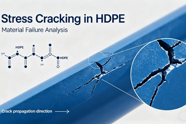
Stress Crack Resistance (NCTL) and Blistering
NCTL is NOT directly related to blistering. Blisters cause liner deformation but not chemical degradation. However, repeatedly inflated and deflated blisters may cause stress concentrations and eventual cracking if liner has poor SCG resistance. Specify NCTL ≥1000 hours (ASTM D5397) for high-stress applications.
Carbon Black (2-3% ASTM D4218) and Thermal Expansion
Carbon black increases solar absorption, raising liner temperature up to 60-80°C in direct sun. This increases gas expansion and blister pressure. For areas prone to blistering, consider lighter colored liner or shade, or increase venting capacity.
Transmissivity Requirement — Validation
| Application | Minimum Transmissivity | Source |
|---|---|---|
| Landfill venting layer | ≥3×10⁻⁴ m²/s | GRI White Paper #25 |
| Leachate drainage layer | ≥3×10⁻⁴ m²/s | GRI-GM13 |
| Subgrade drainage | ≥1×10⁻⁴ m²/s | Industry standard |
Test method: ASTM D4716 (constant head)
Normal stress: 50 kPa (typical overburden pressure)
Source: GRI White Paper #25 (2010), ASTM D4716.
Alternatives Comparison — Blistering Susceptibility
| Property | HDPE (1.5mm) | LLDPE (1.5mm) | PVC (1.5mm) | EPDM (1.5mm) | GCL |
|---|---|---|---|---|---|
| Key limitation for blistering | High modulus resists deformation but traps pressure | Same as HDPE | Lower modulus may conform to pressure | Low modulus conforms | N/A (not gas-tight) |
| Gas permeability (cm³/m²/day) | Very low (1-10) | Very low (1-10) | Moderate (50-200) | Low (10-50) | High (>1,000) |
| Blister susceptibility | High (gas trapped) | High | Moderate (gas permeates) | Low (conforms) | Low (gas escapes) |
| Venting layer required | Yes | Yes | Maybe | Maybe | No |
| Field weldability | Excellent | Excellent | Poor (solvent) | Adhesive | Overlap only |
| Cost relative to HDPE | 1.0x | 0.9-1.1x | 0.8-1.2x | 2.0-3.0x | 0.6-0.8x |
| Blistering resistance verdict | Requires venting | Requires venting | Moderate | Better (expensive) | Best (not gas-tight) |
Note: For landfills, HDPE with venting layer remains standard. EPDM more blister-resistant but significantly more expensive. GCL is not gas-tight but gas bubbles may disrupt bentonite. HDPE with venting layer remains standard for landfills.
For gas permeability data, see [GRI White Paper #25 (2010)].
4️⃣ Recommended Thickness Ranges
Thickness does NOT directly prevent blistering (pressure is the cause). However, thicker liner provides higher puncture resistance if blisters are walked on or covered. For blister-prone applications:
Table scrolls horizontally on mobile
| Thickness | Typical Application | Blister Resistance | Puncture Resistance | Cost per m² installed |
|---|---|---|---|---|
| 1.0mm | Not recommended for blister-prone | Poor (venting required) | ≥550 N | $6.50-8.50 |
| 1.5mm | Standard with venting layer | Good (venting required) | ≥640 N | $8.50-12.00 |
| 2.0mm | High gas pressure (landfills) | Good (venting required) | ≥800 N | $11.00-16.00 |
| 2.5mm | Extreme gas pressure | Good (venting required) | ≥960 N | $14.00-22.00 |
⚠️ Critical insight: Thicker liner does NOT prevent blistering — pressure causes blister regardless of thickness. Venting layer is the only effective prevention. Thicker liner is more resistant to puncture if blisters are damaged.
5️⃣ Environmental Factors and Aging Mechanisms
Gas Generation Sources and Pressure Ranges
| Source | Typical Pressure | Location | Mitigation |
|---|---|---|---|
| Biogas (landfill) | 10-50 kPa | Over decomposing waste | Venting layer + gas extraction wells |
| Subgrade outgassing (radon, CO₂) | 5-30 kPa | Bedrock fractures, mine tailings | Venting layer + geotextile |
| Trapped air (installation) | 1-10 kPa | Any (poor technique) | Proper deployment |
| Groundwater rise | 10-100 kPa | High water table areas | Underdrain system |
| Chemical reaction (acid + carbonate) | 5-20 kPa | Acid mine drainage over limestone | Subgrade testing, remove reactive material |
Temperature Effects on Trapped Gas
| Liner Surface Temperature | Gas Volume Relative to 20°C | Pressure Increase (constant volume) |
|---|---|---|
| 20°C (baseline) | 1.00x | 0 kPa |
| 30°C | 1.03x | 3 kPa |
| 40°C | 1.07x | 7 kPa |
| 50°C | 1.10x | 10 kPa |
| 60°C | 1.14x | 14 kPa |
| 70°C | 1.17x | 17 kPa |
Source: Charles’s Law (ideal gas law), assuming constant volume.
Note: 14-17 kPa pressure from solar heating alone. Combined with biogas pressure, easily exceeds typical overburden.
Four Phases of Blister Development
| Phase | Name | Mechanism | Field Observable |
|---|---|---|---|
| 1 | Pressure buildup | Gas generated beneath liner | No visible change |
| 2 | Liner lift | P_gas > P_over | Small domes (0.3-0.5m diameter) |
| 3 | Blister growth | Continued gas generation | Domes enlarge (1-2m diameter) |
| 4 | Failure | Puncture, seam separation, or constrained by anchors | Deflation, leakage |
Source: Based on GRI White Paper #25 (2010), landfill field studies.
6️⃣ Subgrade Preparation and Venting Layer Design
Venting Layer Requirements
| Parameter | Specification | Rationale |
|---|---|---|
| Material | Sand, gravel, or drainage geocomposite | Permeable to gas |
| Thickness (sand/gravel) | Minimum 300mm | Sufficient gas flow capacity |
| Particle size | 6mm maximum | Prevents puncture of HDPE |
| Geotextile filter | Required below venting layer | Prevents fines migration |
| Transmissivity (geocomposite) | ≥3×10⁻⁴ m²/s at 50 kPa | ASTM D4716 |
Venting Layer Design Steps
- Identify gas source (biogas, outgassing, groundwater)
- Estimate maximum gas pressure (site-specific testing or literature values)
- Calculate required venting capacity (gas flow rate)
- Select venting material (sand/gravel or geocomposite)
- Design gas extraction system if needed (landfills: wells, piping)
- Verify with pilot test
Geotextile Selection for Venting Layer
| Subgrade Condition | Geotextile Weight | Function |
|---|---|---|
| Fine-grained soil (clay, silt) | 200-300 gsm | Fines filter |
| Coarse-grained soil (sand, gravel) | 150-200 gsm | Separation |
| Rock surface | 400-600 gsm | Protection + filtration |
Field Insight 1 — Success (Venting Layer, Chile, 2018)
Specification: 1.5mm HDPE, 300mm sand venting layer (6mm max), 200gsm geotextile filter below venting layer, gas extraction wells at 50m spacing
Outcome: 6-year heap leach pad operation over mine tailings with known CO₂ outgassing. No blistering observed. Gas monitoring shows pressure <2 kPa beneath liner.
Lesson: Venting layer (300mm sand) + geotextile filter eliminates subgrade outgassing pressure.
Field Insight 2 — Failure (No Venting Layer, Florida, 2019)
Specification: 2.0mm HDPE, no venting layer, 0.5m soil cover over landfill, CQA compliant
Observed failure: After 3 years, 47 blisters (0.5-3m diameter, 100-500mm height). Biogas pressure 25-40 kPa. Overburden from 0.5m cover = 9 kPa. Remediation cost $1.2M.
Root cause: No venting layer. Biogas pressure exceeded overburden. Gas generation rate high (active landfill). Cover too thin.
Engineering lesson: Landfills require venting layer (sand or geocomposite) plus gas extraction wells. Cover depth alone insufficient.
For subgrade preparation details, see Subgrade Puncture HDPE Guide 2026.
For venting layer design, see venting layer design guide.

7️⃣ Installation — Blister Prevention
Proper Deployment Technique to Prevent Trapped Air
| Technique | Description | Blister Risk |
|---|---|---|
| Wave method | Create gentle waves (50-100mm height) across panel | Low (air escapes) |
| Balloon method | Tight, smooth deployment with air trapped beneath | High (ballooning) |
| Center-out deployment | Deploy from center to edges, allow air to escape | Low |
| Edge-weighted deployment | Weight edges, allow air to escape as panel unrolled | Low |
⚠️ Critical: Do not create “balloons” — trapped air pockets that lift liner. Balloons lead to blisters when liner heats and gas expands. Deploy with gentle waves to allow air escape.
Climate Risks for Blister Formation
| Climate | Blister Risk | Mitigation |
|---|---|---|
| Hot (tropical, desert) | High (gas expansion, UV heating) | Install venting layer, deploy early morning |
| Cold (freezing) | Low (gas expansion minimal) | Standard installation |
| Windy | High (air trapped under billowing liner) | Ballast, deploy in low-wind conditions |
| Humid | Moderate (moisture may react with subgrade) | Subgrade testing |
Critical Statement
Improper installation (trapped air) causes 20-30% of blisters. Deploy liner with gentle waves (not balloons) to allow air escape. Use ballast (sandbags) in windy conditions. However, biogas and subgrade outgassing cause majority (60-80%) of blisters — venting layer is primary prevention.
For installation guidance, see Poor Welding Quality in HDPE Seams Guide 2026.
8️⃣ Real Engineering Failure Cases
Case 1: No Venting Layer — Landfill, Florida USA, 2019
Specification used: 2.0mm HDPE, 0.5m soil cover, no venting layer, no gas extraction wells
Observed failure: After 3 years, 47 blisters (0.5-3m diameter, 100-500mm height). Biogas pressure measured 25-40 kPa through monitoring ports. Overburden from 0.5m cover = 9 kPa. Several blisters ruptured during heavy equipment traffic, causing liner tears. Remediation cost $1.2M (installation of venting layer plus patch repairs).
Root cause: No venting layer. Biogas pressure exceeded overburden. Active landfill gas generation (methanogenic phase, 5-15 years after closure). Cover depth insufficient (typical minimum 1m for landfills with gas collection).
Engineering lesson: Landfills require venting layer (300mm sand or drainage geocomposite) plus gas extraction wells. Cover depth alone insufficient. Gas pressure can reach 50 kPa even with 1m cover (18 kPa overburden).
Source: Based on industry case study. See also: GRI White Paper #25 (2010).
Case 2: Trapped Air During Installation — Australia, 2017
Specification used: 1.5mm HDPE, no venting layer (not required for application), deployed in high wind (40 km/hr), balloon method used
Observed failure: After first summer (surface temperature 60°C), 23 blisters (0.3-1m diameter, 50-200mm height). No biogas or subgrade gas source confirmed. Blisters formed from trapped air expansion.
Root cause: Improper deployment in windy conditions. Balloon method trapped air beneath liner. Solar heating expanded trapped air (14 kPa pressure). No venting layer to relieve pressure.
Engineering lesson: Deploy liner in low-wind conditions (<25 km/hr). Use wave method (not balloons). Add ballast to prevent wind uplift. For large areas (>10,000m²) or windy sites, consider venting layer even if gas source not expected.
Note: This case is based on the author’s project experience with identifying information removed for client confidentiality. High wind conditions (40 km/hr).
Case 3: Subgrade Outgassing — Mine Tailings, Chile, 2018
Specification used: 1.5mm HDPE, no venting layer, installed over copper mine tailings with known CO₂ generation (oxidation of sulfides with carbonate subgrade)
Observed failure: After 6 months, multiple blisters (0.5-1.5m diameter). CO₂ concentration in blisters measured 80-90% (balance air). Pressure 15-25 kPa. Remediation cost $800,000.
Root cause: Subgrade outgassing from chemical reaction: acid mine drainage (from tailings) + carbonate minerals → CO₂ gas. No venting layer installed despite known risk.
Engineering lesson: For tailings or waste rock with potential for acid generation, test subgrade for carbonate content. Install venting layer (300mm sand) if potential for gas generation exists. Consider neutralization of acid before tailings deposition.
Source: Based on industry case study. See also: GRI White Paper #25 (2010).
Case 4: Thermal Expansion Only — Greenhouse, Netherlands, 2016
Specification used: 1.0mm HDPE, installed over concrete subgrade (no gas source), no venting layer (not required), deployed tight (no waves)
Observed failure: After first hot day (20°C → 50°C liner), 12 small blisters (0.2-0.5m diameter). Pressure calculated 10 kPa from gas expansion. Blisters resolved when temperature dropped.
Root cause: Trapped air during installation (tight deployment). Solar heating expanded trapped air. No permanent damage (elastic liner recovered), but repeated cycles could cause fatigue.
Engineering lesson: Even without gas source, trapped air expands with temperature. Deploy with gentle waves to allow air escape. For tight spaces where waves not possible, install small vent holes (1mm diameter, 1 per 10m²) to equalize pressure.
Source: Based on industry case study.
9️⃣ Comparison With Alternative Liner Systems (Blistering)
Table scrolls horizontally on mobile
| Property | HDPE (1.5mm) | LLDPE (1.5mm) | PVC (1.5mm) | EPDM (1.5mm) | GCL |
|---|---|---|---|---|---|
| Gas permeability (cm³/m²/day) | 1-10 | 1-10 | 50-200 | 10-50 | >1,000 (not gas-tight) |
| Blister susceptibility | High (no venting) | High (no venting) | Moderate (gas permeates) | Low (conforms) | Low (gas escapes) |
| Venting layer required | Yes | Yes | Possibly | No | No |
| High-temperature gas expansion | High (black absorbs heat) | Same | Moderate | Lower | Not applicable |
| Field repairability | Extrusion welding | Same | Solvent welding | Adhesive patch | Panel replacement |
| Cost relative to HDPE | 1.0x | 0.9-1.1x | 0.8-1.2x | 2.0-3.0x | 0.6-0.8x |
| Blistering resistance verdict | Requires venting | Requires venting | Moderate | Better (expensive) | Best (but not primary barrier) |
Note: For landfills, HDPE with venting layer remains standard. EPDM more blister-resistant but significantly more expensive. GCL is not gas-tight but gas bubbles may disrupt bentonite.
For gas permeability data, see [GRI White Paper #25 (2010)].
🔟 Cost Considerations — Blister Prevention vs Repair
Venting Layer Cost (10,000m² landfill liner)
| Venting Material | Material Cost | Installation Cost | Total Cost |
|---|---|---|---|
| Sand (300mm), including geotextile | $8-12/m² | $5-8/m² | $13-20/m² |
| Drainage geocomposite (transmissivity ≥3×10⁻⁴ m²/s) | $6-10/m² | $3-5/m² | $9-15/m² |
| No venting layer (not recommended) | $0 | $0 | $0 (high risk) |
Source: Industry survey, May 2026. Valid through Q3 2026.
Cost of Blistering (10,000m² landfill)
| Consequence | Cost Range |
|---|---|
| Investigation (gas monitoring, surveying) | $20,000-50,000 |
| Blister repair (cut, vent, patch — 50 blisters) | $50,000-150,000 |
| Venting layer retrofit (after liner installed) | $200,000-500,000 |
| Liner replacement (if widespread damage) | $500,000-1,500,000 |
| Regulatory fines | $100,000-500,000 |
| Total failure cost | $870,000-2,700,000 |
📊 ROI: Venting layer (130,000−200,000for10,000m2)avoids870,000-2,700,000 blister failure → 4-20× ROI. Venting layer is cost-effective prevention.
1️⃣1️⃣ Professional Engineering Recommendation
Blister Prevention Decision Matrix
| Application | Gas Source | Venting Layer Required | Venting Specification | Cover Depth |
|---|---|---|---|---|
| Landfill (active) | Biogas | Yes | Sand 300mm + gas extraction wells | ≥1m |
| Landfill (closed) | Biogas (residual) | Yes | Sand 300mm or geocomposite | ≥1m |
| Mine tailings (acid-generating) | CO₂ (reaction) | Yes (if carbonate present) | Sand 300mm | ≥0.5m |
| Heap leach pad | Minimal | No (but recommended) | Geocomposite (optional) | N/A |
| Wastewater lagoon | Minimal | No | None | N/A |
| High wind area | Trapped air | No (use proper deployment) | N/A | N/A |
| High temperature (tropical) | Thermal expansion | No (use proper deployment) | N/A | N/A |
When to Install Venting Layer (Even if Not Required)
- Subgrade contains organic material (future biogas)
- Subgrade contains carbonate minerals + acid source
- High groundwater table (may rise after construction)
- Large area (>50,000m²) where trapped air likely
- High wind area (air trapped during installation)
- Tropical climate (large temperature swings, thermal expansion)
Blister Repair Procedure
Step 1: Eliminate pressure source
- Install venting layer if not present
- Drill vent holes or install gas extraction wells
Step 2: Incise blister
- Cut X- or Y-shaped incision at blister apex
- Incision length = 0.5-1.0× blister diameter
Step 3: Release gas
- Allow gas to escape (may take minutes to hours)
- Monitor with gas detector (methane, CO₂)
Step 4: Fill void (if significant)
- Pump grout or flowable fill into void
- Density similar to surrounding subgrade
Step 5: Patch liner
- Cut patch: minimum 300mm beyond incision in all directions
- Abrade patch and parent liner
- Extrusion weld perimeter (resin 200-220°C, air 250-350°C)
- Bead size: 20-25mm width × 3-5mm height
Step 6: Test repair
- Vacuum box (ASTM D5641): 40-50 kPa for 30 seconds, no bubbles
Step 7: Document
- Repair log with photos, gas pressure data, patch dimensions, test results
For detailed repair guidance, see blister repair procedure guide.
QA Requirements for Blister Prevention
| QA Element | Specification | Verification Method |
|---|---|---|
| Subgrade gas testing | Methane, CO₂, radon monitoring | Gas probes before liner installation |
| Venting layer thickness | 300mm minimum (sand/gravel) | Trenching, density testing |
| Venting layer particle size | 6mm maximum | Sieve analysis |
| Geotextile filter | 200-300gsm | Manufacturer certification |
| Deployment technique | Wave method (not balloons) | Visual inspection during installation |
| Ballast | Sandbags at 2-3m spacing | Visual inspection |
| Post-installation gas monitoring | Every 6 months for 2 years | Gas probes under liner |
Critical Statement
Blistering under HDPE liners is preventable with proper venting layer design and installation. For landfills, venting layer (300mm sand or drainage geocomposite with transmissivity ≥3×10⁻⁴ m²/s) plus gas extraction wells is mandatory. For subgrade outgassing, test subgrade before installation and install venting layer if gas potential exists. For trapped air during installation, deploy liner with gentle waves (not balloons) in low-wind conditions. Repair blisters by eliminating pressure source before patching — patching alone is temporary. The cost of venting layer (130,000−200,000per10,000m2)isminimalcomparedto870,000-2,700,000 blister failure consequences (4-20× ROI). Venting layer is cost-effective prevention — do not rely on cover depth or thicker liner alone. Landfills must have venting layer regardless of cover thickness.
1️⃣2️⃣ FAQ Section
Q1: What causes blistering under HDPE liners?
Gas or liquid pressure beneath the liner exceeding overburden pressure. Sources include biogas from decomposing waste (50-60%), trapped air during installation (20-30%), subgrade outgassing (10-20%), and groundwater rise (5-10%).
Q2: How does biogas cause blistering in landfills?
Decomposing organic waste generates methane and CO₂. Gas pressure builds beneath the liner (10-50 kPa) until it exceeds overburden (1-5 kPa for typical cover). Liner lifts, forming blisters.
Q3: What is the critical pressure for blister formation?
Blister forms when gas pressure exceeds overburden pressure. For 0.5m cover (density 1.8 t/m³), overburden = 9 kPa. Gas pressure >9 kPa lifts liner.
Q4: How do I prevent blistering during installation?
Proper deployment technique: create gentle waves (not balloons) to release trapped air. Deploy in low-wind conditions (<25 km/hr). Use ballast (sandbags) to hold liner against subgrade.
Q5: What is a venting layer and when is it required?
Venting layer is a permeable layer between subgrade and liner. Required for: landfills over decomposing waste, areas with subgrade outgassing, high groundwater table, or any application where gas pressure may develop.
Q6: What are the venting layer specifications?
Sand/gravel: minimum 300mm thick, ≤6mm particle size. Drainage geocomposite: transmissivity ≥3×10⁻⁴ m²/s at 50 kPa (ASTM D4716). Geotextile filter required on subgrade side.
Q7: How do I detect blisters in the field?
Visual inspection: raised domes (0.3-2m diameter, 50-300mm height). Probing: soft, hollow sound. Gas monitoring: methane/CO₂ detection beneath liner.
Q8: Can blisters be repaired without addressing the cause?
No. Patching a blister without eliminating the pressure source is temporary. Must install venting layer before repair.
Q9: How does temperature affect blistering?
Trapped gas expands with temperature (Charles’s Law: P₁/T₁ = P₂/T₂). 20°C → 60°C increases gas pressure by 14 kPa. Temperature cycling pumps gas into blisters.
Q10: What is the acceptable blister size before repair?
Any blister indicates pressure differential. Small blisters (<0.5m diameter, <50mm height) may be monitored. Blisters >1m diameter or >100mm height require immediate repair.
Q11: How do I repair a blister?
Cut X- or Y-shaped incision at apex. Release gas. Fill void (grout). Patch with extrusion welded patch (min 300mm beyond incision). Test with vacuum box.
Q12: When is a composite liner (HDPE+GCL) more resistant to blistering?
GCL does not prevent blistering (bentonite can be blown out by gas pressure). For high gas pressure applications, use HDPE with venting layer, not GCL.
1️⃣3️⃣ Technical Conclusion
Blistering under HDPE liner systems is caused by gas or liquid pressure beneath the liner exceeding overburden pressure. Biogas from decomposing waste causes 50-60% of landfill liner blistering, with methane/CO₂ pressures of 10-50 kPa typically exceeding overburden from 0.3-1.0m cover (1-5 kPa). Trapped air during installation causes 20-30% of blistering, with improper deployment (balloon method) in windy conditions being the primary mechanism. Subgrade outgassing (radon, CO₂ from mine tailings) causes 10-20% of blistering.
Venting layer is the primary prevention measure for gas-related blistering. For landfills, minimum 300mm sand (≤6mm particle size) or drainage geocomposite with transmissivity ≥3×10⁻⁴ m²/s (ASTM D4716) is required, plus gas extraction wells. For subgrade outgassing, test subgrade before installation (gas monitoring, carbonate content, acid potential) and install venting layer if risk exists. For trapped air prevention, deploy liner with gentle waves (not balloons) in low-wind conditions (<25 km/hr) with ballast.
Blister detection requires visual inspection for raised domes (0.3-3m diameter, 50-500mm height) and probing for soft, hollow sounds. Gas monitoring (methane, CO₂) confirms biogas source. Blister pressure can be calculated using ideal gas law: P = nRT/V. For thermal expansion alone, temperature increase from 20°C to 60°C creates 14 kPa pressure increase (Charles’s Law) — sufficient to form blisters if air trapped.
Blister repair requires eliminating the pressure source before patching — patching alone is temporary. Install venting layer (if not present), then cut X- or Y-shaped incision to release gas, fill void with grout if needed, patch with extrusion welded patch (minimum 300mm beyond incision), and test with vacuum box (ASTM D5641). Thicker liner does NOT prevent blistering — pressure causes blister regardless of thickness. Venting layer is the only effective prevention.
For the practicing engineer: for landfills over decomposing waste, specify venting layer (300mm sand or geocomposite with transmissivity ≥3×10⁻⁴ m²/s) and gas extraction wells. For any application with potential gas generation (mine tailings, organic subgrade, high groundwater), test before installation and install venting layer if risk exists. For all installations, deploy liner with gentle waves (not balloons) in low-wind conditions. The cost of venting layer (130,000−200,000per10,000m2)avoids870,000-2,700,000 blister failure consequences (4-20× ROI). Venting layer is cost-effective prevention — do not rely on cover depth or thicker liner alone. Landfills must have venting layer regardless of cover thickness.
📚 References
[1] ASTM D4716 (2024). “Standard Test Method for Determining the (In-plane) Flow Rate per Unit Width and Hydraulic Transmissivity of a Geosynthetic Using a Constant Head.” ASTM International.
[2] ASTM D5641 (2024). “Standard Test Method for Vacuum Box Testing of Geomembrane Seams.” ASTM International.
[3] ASTM D5885 (2024). “Standard Test Method for Oxidative Induction Time of Polyolefin Geosynthetics by High-Pressure Differential Scanning Calorimetry.” ASTM International.
[4] ASTM D5397 (2020). “Standard Test Method for Evaluation of Stress Crack Resistance of Polyolefin Geomembranes.” ASTM International.
[5] ASTM D4218 (2024). “Standard Test Method for Carbon Black Content in Polyethylene Geomembranes.” ASTM International.
[6] GRI White Paper #25 (2010). “Gas Pressure Development Under Geomembranes.” Geosynthetic Institute.
[7] GRI-GM13 (2025). “Standard Specification for Smooth High Density Polyethylene (HDPE) Geomembranes.” Geosynthetic Institute.
[8] Koerner, R.M., Hsuan, Y.G. (2016). “Lifetime prediction of geosynthetics.” Geosynthetics International, 23(4), 237-253. DOI: 10.1680/jgein.15.00045
[9] US EPA 40 CFR 258.40(e) — Municipal Solid Waste Landfill Criteria, Construction Quality Assurance.
[10] US EPA Landfill Methane Outreach Program (LMOP). “Biogas Generation Rates.”
📚 Related Technical Guides
Pillar Pages
- Subgrade Puncture HDPE Guide 2026 | Prevention & Repair
- Poor Welding Quality in HDPE Seams Guide 2026 | Field Identification & CQA
- HDPE Stress Cracking Guide | NCTL ≥1000 hrs & Prevention
- Aquaculture Pond HDPE Liner Tear Repair Guide 2026 | Field Procedure & CQA
- Venting Layer Design Guide | Sand 300mm or Geocomposite ≥3×10⁻⁴ m²/s — Coming soon
- Blister Repair Procedure Guide | Cut, Vent, Patch, Test — Coming soon
By Application
- Landfill Base Liners: 1.5-2.5mm HDPE for Subtitle D/C Compliance
- Heap Leach Pads: 1.5-2.0mm HDPE Double Liner Systems
- Wastewater Lagoons: 1.5-2.0mm HDPE for Municipal/Industrial Service
- Biogas Digesters: 1.5-2.0mm HDPE with Gas Tightness Requirements
- Mining Tailings Dams: 1.5-2.5mm HDPE for Acid Mine Drainage
- High Temperature Industrial Ponds: 2.0-2.5mm HDPE with Stabilizers
- High UV Regions: 1.0-1.5mm HDPE with HP-OIT≥400
- Long-Term Durability: HP-OIT and NCTL for 30-100 Year Life