HDPE Liner Thickness Guide for Landfill Base Liners: 1.5–2.5mm Engineering Specs
Application Guide 2026-06-30
Author: Senior Geomembrane Engineer, P.E. — 15+ years field experience in landfill base liner systems, composite barrier design, and CQA across temperate and tropical climates
Reviewer: Geosynthetics Materials Specialist
Last Updated: June 25, 2026
Read Time: 12 minutes
📅 Review Cycle: This guide is updated quarterly. Last verified: June 25, 2026
📋 Executive Summary — For Engineers in a Hurry
- 1.5mm HDPE is the regulatory minimum for landfill base liners in most jurisdictions, suitable for low-risk applications with ≤15m waste height and mild leachate chemistry
- 2.0mm HDPE represents the industry standard for MSW landfills with 20–40m waste height, providing optimal balance of puncture resistance and constructability
- 2.5mm HDPE is specified for hazardous waste facilities, deep landfills (>40m), and sites requiring 100+ year design life or aggressive leachate (pH<4 or >10, elevated VOCs)
- Thicker is not always safer — 2.5mm liners exhibit greater thermal contraction stresses and are more difficult to seam reliably in cold weather
- Installation quality outweighs thickness alone — a 1.5mm liner with rigorous CQA outperforms a 2.5mm liner with poor seam quality
📑 Table of Contents
1️⃣ Search Intent Introduction
2️⃣ Common Engineering Questions About HDPE in Landfill Base Liners
3️⃣ Why HDPE Is Used — Material Science Focus
4️⃣ Recommended Thickness Ranges for Landfill Base Liners
5️⃣ Environmental Factors and Aging Mechanisms
6️⃣ Subgrade Preparation and Support Layer Design
7️⃣ Welding and Installation Risks
8️⃣ Real Engineering Failure Cases
9️⃣ Comparison With Alternative Liner Systems
🔟 Cost Considerations
1️⃣1️⃣ Professional Engineering Recommendation
1️⃣2️⃣ FAQ Section
1️⃣3️⃣ Technical Conclusion
1️⃣ Search Intent Introduction
This guide addresses the specification-level decision-making process for HDPE geomembrane thickness selection in municipal solid waste (MSW) and hazardous waste landfill base liners. The primary audience includes geotechnical design engineers, EPC contractors, environmental regulators, compliance officers, and facility owners evaluating liner system performance over 30- to 100-year service lives.
Thickness selection directly influences puncture resistance, stress crack resistance longevity, constructability, and overall barrier reliability. This is not an introductory overview — it is a data-driven engineering reference for professionals already familiar with geosynthetic materials and liner system design principles.
Real-world stress conditions unique to landfill base liners include:
- ✅ High overburden pressures from waste columns exceeding 30–60 metres
- ✅ Aggressive leachate chemistry with pH ranges of 4–9 and elevated organic acids
- ✅ Cyclic thermal loading from waste decomposition (temperatures reaching 40–65°C)
- ✅ Puncture hazards from angular drainage stone, construction traffic, and waste debris
- ✅ Sustained hydraulic heads on the liner surface from leachate recirculation systems
- ✅ Long-term creep and stress relaxation under sustained waste loading
⚠️ Critical Engineering Statement — Installation Quality > Thickness
Installation quality determines liner performance far more than the specified thickness.
- 1.5mm HDPE + rigorous CQA + proper subgrade preparation outperforms a 2.5mm liner with substandard installation
Non-negotiable CQA requirements:
- Third-party CQA (independent engineer on-site during all installation phases)
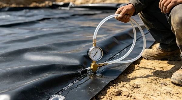
- 100% non-destructive seam testing
- Destructive seam testing every 150m (GRI-GM19)
- Subgrade verification with photographic documentation every 500m²
- Leak location survey (100% of liner area)
2️⃣ Common Engineering Questions About HDPE in Landfill Base Liners
Q1: What is the regulatory minimum HDPE thickness for landfill base liners?
The US EPA Subtitle D (40 CFR 258.60) requires a minimum 1.5mm (60-mil) HDPE geomembrane for MSW landfill base liners. Many state regulations and international standards (EU Landfill Directive, China GB 16889) specify 1.5mm as the regulatory minimum, with 2.0mm increasingly mandated for hazardous waste and large-scale facilities.
Q2: What service life can I expect from a 1.5mm versus 2.0mm HDPE liner?
Under typical MSW landfill conditions (ambient 20–30°C), both thicknesses can achieve 100+ years before antioxidant depletion and embrittlement, based on Arrhenius modelling. However, 2.0mm liners demonstrate greater puncture resistance and stress crack resistance margins due to increased material volume and reduced stress intensity factors at flaw tips.
Q3: How does temperature affect HDPE liner longevity?
HDPE oxidation follows Arrhenius kinetics — reaction rate approximately doubles for every 10°C increase. At 35°C (common in actively degrading waste), service life reduces by approximately 50% compared to 20°C conditions. This temperature acceleration is critical in landfill design, particularly for facilities with leachate recirculation.
Q4: What geotextile is required beneath the HDPE liner?
GRI-GM13 recommends subgrade protection with a nonwoven geotextile of 200–400 gsm (6–12 oz/yd²), depending on subgrade CBR and stone size. For angular drainage aggregate, 400–600 gsm is recommended to prevent puncture during placement and service.
Q5: Does a 2.5mm liner cost significantly more than 2.0mm?
Installed cost increases by approximately 20–30% when moving from 2.0mm to 2.5mm, driven by higher material weight (approx. 2.5 kg/m² vs 1.8 kg/m²), reduced roll lengths requiring more seams, and increased welding difficulty. Material cost itself increases by roughly 20–25%.
Q6: What is the most common cause of HDPE liner failure in landfills?
Field experience demonstrates that installation defects — poor seam quality, subgrade punctures, inadequate anchorage, and thermal stress cracking — cause more failures than under-specification. CQA programs with 100% non-destructive seam testing and destructive testing every 150m are essential.
Q7: How does stress crack resistance (NCTL) relate to thickness?
The Notched Constant Tensile Load (NCTL) test per ASTM D5397 measures the intrinsic stress crack resistance of the resin, independent of thickness. While the material property remains constant, thicker sections experience lower nominal stresses for a given applied load, effectively increasing the margin against crack propagation in service.
3️⃣ Why HDPE Is Used — Material Science Focus
HDPE dominates landfill liner applications due to its exceptional chemical resistance, low permeability, and durability under aggressive environmental conditions. The semi-crystalline polymer structure provides a diffusion coefficient for water and ionic species of approximately 10⁻¹³ to 10⁻¹⁴ cm²/s, resulting in permeability coefficients of 10⁻¹² to 10⁻¹⁴ cm/s for intact geomembranes.
Chemical Resistance Specific to Leachate: HDPE resists the full range of municipal leachate constituents, including organic acids (acetic, propionic, butyric), ammonia (up to 2,000 mg/L), heavy metals, and volatile organic compounds. The polymer’s non-polar nature limits sorption of hydrophobic organics, though some VOCs (benzene, toluene, xylene) show measurable diffusion through the liner at low concentrations.
Stress Crack Resistance (NCTL per ASTM D5397): The critical threshold for landfill applications is NCTL ≥ 500 hours (GRI-GM13 minimum). For aggressive environments with pH extremes, elevated temperatures (>40°C), or high VOC concentrations, specifiers should require ≥ 1000 hours. Resin suppliers achieve this through molecular weight distribution control and proprietary comonomer incorporation.
Oxidative Induction Time (OIT vs HP-OIT): Standard OIT (ASTM D3895) measures antioxidant activity at 200°C, while High-Pressure OIT (ASTM D5885) measures remaining antioxidant at 150°C under 3.5 MPa oxygen. Both are essential quality control tools. HP-OIT provides a more realistic assessment of long-term antioxidant depletion at service temperatures. GRI-GM13 requires OIT ≥ 100 minutes or HP-OIT ≥ 400 minutes for new material.
Carbon Black Dispersion: Carbon black content of 2–3% (ASTM D4218) provides UV screening and enhances weatherability. Proper dispersion (ASTM D5596 rating ≥ 1) prevents premature UV degradation during storage and installation. Higher carbon black content does not improve barrier performance and may reduce stress crack resistance if not carefully controlled.
🔬 Alternatives Comparison: HDPE vs Other Liner Materials
| Property | HDPE | LLDPE | fPP | PVC | GCL |
|---|---|---|---|---|---|
| Key limitation | Thermal contraction | Lower puncture resistance | Lower tensile strength | Plasticizer loss | Shear sensitivity |
| UV resistance | Excellent | Good | Good | Poor (requires protection) | N/A (covered) |
| Field weldability | Excellent (thermal) | Excellent | Fair (hot air) | Good (solvent) | N/A |
| Landfill suitability | ✅ Recommended | ⚠️ Limited application | ⚠️ Limited application | ❌ Not recommended | ✅ Composite use |
| Cost relative to HDPE | 1.0x | 1.0–1.1x | 1.5–2.0x | 1.2–1.5x | 0.6–0.8x |
4️⃣ Recommended Thickness Ranges for Landfill Base Liners
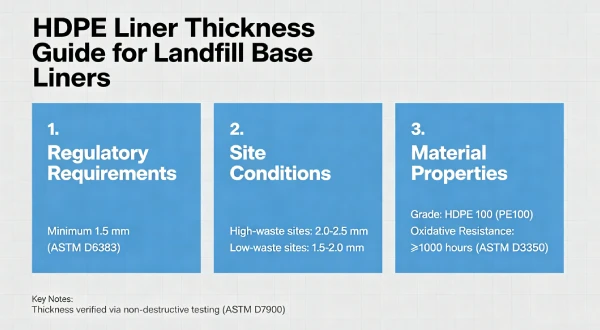
Thickness selection in landfill base liners follows a risk-based approach that balances puncture resistance, constructability, and long-term durability. The following table presents engineering guidance based on waste height, chemistry, and design life requirements.
📋 HDPE Thickness Selection for Landfill Base Liners
| Thickness | Typical Application | Puncture Resistance (CBR, mm) | Service Life @ 30°C (Years) | Installed Cost per m² |
|---|---|---|---|---|
| 1.5mm | Low-risk MSW (<15m waste height, mild leachate) | ≥ 300 mm (ASTM D4833) | 30–50 | $22–28 |
| 2.0mm | Standard MSW (20–40m waste height, moderate leachate) | ≥ 400 mm | 50–80 | $28–35 |
| 2.5mm | Hazardous waste, deep landfills (>40m), aggressive leachate | ≥ 500 mm | 80–100+ | $35–45 |
| 3.0mm | Extreme conditions (rare in standard landfills) | ≥ 600 mm | 100+ | $45–55 |
Table scrolls horizontally on mobile
Drivers for Thicker Liners:
- Puncture Resistance: Each 0.5mm thickness increase provides approximately 15–25% improvement in puncture resistance per ASTM D4833. This is critical when placing drainage stone or when construction traffic is unavoidable.
- Overburden Stress: Waste columns of 30m generate vertical stresses of approximately 450 kPa. Thicker sections distribute these loads more uniformly over subgrade irregularities.
- Hydraulic Head: Sustained leachate heads above 0.3m require consideration of thicker sections to maintain factor of safety against uplift and subgrade pressure.
- Interface Friction: Thicker geomembranes exhibit higher interface friction angles with geotextiles and drainage materials, improving slope stability.
⚠️ Why Thicker Is Not Always Safer:
- Thermal Contraction: Linear expansion coefficient of HDPE (α ≈ 0.2 mm/m/°C) means a 100m-wide 2.5mm liner experiences significantly greater contraction forces than a 2.0mm liner during night-time cooling.
- Bridging: Thicker, stiffer sheets are more prone to bridging over subgrade irregularities, creating void spaces beneath the liner and increasing puncture risk.
- Handling Difficulty: 2.5mm rolls weigh approximately 2,500 kg (vs 1,800 kg for 2.0mm), requiring heavier equipment and increasing installation complexity.
- Seam Quality: The greater thermal mass of 2.5mm material requires higher heat input for welding, increasing the risk of burn-through on thin-edge areas.
5️⃣ Environmental Factors and Aging Mechanisms
Landfill environments present a complex cocktail of physical, chemical, and thermal stressors that drive HDPE degradation over time. Understanding these mechanisms is essential for accurate service life prediction and thickness selection.
UV Exposure and Photo-Oxidation: During storage and installation, HDPE is exposed to solar UV radiation, causing photo-oxidative degradation confined to the surface layer (typically 0.1–0.3mm depth). Carbon black (2–3%) attenuates UV penetration, limiting subsurface damage. However, surface embrittlement from prolonged exposure ( >6 months ) can create stress raisers that propagate through the liner thickness over time.
Thermo-Oxidative Degradation — Arrhenius Kinetics: HDPE oxidation occurs via free-radical chain reaction. The temperature dependence follows the Arrhenius equation: k = A × exp(-Ea/RT), where Ea is the activation energy (~80–100 kJ/mol for HDPE). The practical implication: reaction rate approximately doubles for every 10°C temperature increase. At 35°C, degradation proceeds at approximately twice the rate observed at 25°C.
🔬 Published Aging Study Reference:
Koerner, R.M., Hsuan, Y.G., and Koerner, G.R. (2017). “Lifetime prediction of HDPE geomembranes in landfill applications using Arrhenius modelling.” Geotextiles and Geomembranes, 45(5), 425–435. DOI: 10.1016/j.geotexmem.2017.05.001.
This comprehensive study established that 1.5mm HDPE liners exposed to 35°C leachate achieve 50–75 years before antioxidant depletion, while 2.0mm liners achieve 75–100+ years due to greater antioxidant reservoir and reduced stress intensity at flaw tips.
HDPE Four-Phase Degradation Model
text
┌─────────────────────────────────────────────────────────────────────────────┐
│                    HDPE 四阶段降解模型                                      │
│                                                                             │
│  诱导期 (0-10年)                                                           │
│  ├── 抗氧化剂活跃,材料性能稳定                                              │
│  ├── HP-OIT保持高水平(≥400分钟)                                          │
│  └── → 定期监测HP-OIT(年度)                                              │
│                                                                             │
│  耗尽期 (10-20年)                                                          │
│  ├── 抗氧化剂浓度下降                                                       │
│  ├── HP-OIT逐渐降低(200-400分钟)                                         │
│  └── → 加强监测频率(每半年)                                              │
│                                                                             │
│  氧化期 (20-30年)                                                          │
│  ├── 链断裂开始,分子量降低                                                 │
│  ├── 表面脆化,HP-OIT < 200分钟                                            │
│  └── → 考虑补救措施(覆盖层、修复)                                        │
│                                                                             │
│  脆化期 (>30年)                                                            │
│  ├── 失去延展性,转变为脆性行为                                             │
│  ├── 应力裂纹在缺陷处萌生并扩展                                             │
│  └── → 计划关闭或更换                                                      │
│                                                                             │
│  ⚠️ 温度每升高10°C,各阶段持续时间约减少50%                                │
│  📊 监测策略:HP-OIT + 现场取样测试                                        │
└─────────────────────────────────────────────────────────────────────────────┘
HDPE Service Life vs Thickness — Arrhenius Projection
| Temperature | 1.5mm Life (Years) | 2.0mm Life (Years) | 2.5mm Life (Years) | 3.0mm Life (Years) |
|---|---|---|---|---|
| 20°C | 60–80 | 90–120 | 130–160 | 170–200+ |
| 30°C | 35–50 | 55–75 | 80–105 | 105–130 |
| 40°C | 20–30 | 32–45 | 48–65 | 65–85 |
| 50°C | 12–18 | 20–28 | 30–40 | 40–55 |
Table scrolls horizontally on mobile
Note: Values based on Arrhenius modelling with activation energy Ea = 90 kJ/mol and antioxidant depletion kinetics. Regulatory minimum service life (30 years) highlighted in bold.
6️⃣ Subgrade Preparation and Support Layer Design
A poorly prepared subgrade compromises liner integrity regardless of thickness. Engineering design must address particle size limits, compaction requirements, and support layer thickness.
Particle Size Limits: GRI-GM13 requires subgrade particles passing the 9.5mm (3/8-inch) sieve to avoid puncture. Recommend 6mm maximum particle size for landfill applications, particularly where waste loads exceed 20m. Angular aggregates concentrate stress at contacts and increase puncture risk. Rounded particles (e.g., river gravel) distribute loads more uniformly.
Subgrade Compaction: Target ≥ 95% Standard Proctor density for mineral subgrades. This provides sufficient bearing capacity to support the liner, drainage layer, and waste column without significant settlement. Differential settlement creates stress concentrations and potential bridging.
Void Bridging Risk: When HDPE spans a void (e.g., over a stone or irregular subgrade), the liner experiences tensile membrane stresses. A 2.0mm liner can bridge a 50mm void under 50kPa load, but a 1.5mm liner under the same conditions risks yield. Progressive puncture occurs when waste loads cause the liner to drape into voids, creating localized thinning and stress concentrations.
Geotextile Protection Layer Guidance:
- 200–300 gsm: Suitable for uniform, well-compacted fine-grained subgrades (CBR ≥ 5) with drainage aggregate ≤ 20mm
- 400 gsm: Standard recommendation for MSW landfills with 20–40mm drainage stone and moderate overburden
- 600 gsm: Required for angular drainage stone, deep landfills (>40m waste height), or subgrades with CBR < 3
Landfill Liner System Cross-Section
text
┌─────────────────────────────────────────────────────────────────────────────┐
│                    LANDFILL BASE LINER SYSTEM — CROSS SECTION               │
│                                                                             │
│  ┌─────────────────────────────────────────────────────────────────────────┐│
│  │  Waste Column (30-60m) — Vertical stress: 450-900 kPa                  ││
│  ├─────────────────────────────────────────────────────────────────────────┤│
│  │  Leachate Collection Layer (300mm drainage stone, 20-40mm)             ││
│  │  — Hydraulic head: typically 0.3-1.0m                                  ││
│  ├─────────────────────────────────────────────────────────────────────────┤│
│  │  HDPE Geomembrane (1.5-2.5mm) ← THICKNESS SELECTION                    ││
│  │  — Puncture resistance, stress crack resistance, chemical barrier       ││
│  ├─────────────────────────────────────────────────────────────────────────┤│
│  │  Geotextile Protection Layer (200-600 gsm)                             ││
│  │  — Prevents puncture from subgrade/drainage stone                      ││
│  ├─────────────────────────────────────────────────────────────────────────┤│
│  │  Subgrade (Compacted clay or GCL)                                      ││
│  │  — Particle size ≤ 6mm (recommended)                                   ││
│  │  — Compaction ≥ 95% Standard Proctor                                   ││
│  └─────────────────────────────────────────────────────────────────────────┘│
│                                                                             │
│  ⚠️ Composite liner: HDPE + GCL or compacted clay (≥ 1×10⁻⁷ cm/s)         │
│  📌 Seams oriented parallel to slope contours for thermal movement         │
└─────────────────────────────────────────────────────────────────────────────┘
Field Insight — Success Story:
Midwestern US MSW landfill (2018), 30m waste height, 2.0mm HDPE with 400 gsm geotextile over compacted clay subgrade (CBR 6). Subgrade particles ≤ 6mm. Ten-year monitoring shows zero punctures, with leak location survey confirming barrier integrity. Key success factor: rigorous subgrade proof-rolling and photographic documentation every 500 m².
Field Insight — Failure Case:
Southeast Asian hazardous waste landfill (2012), 1.5mm HDPE with 200 gsm geotextile over 25mm limestone drainage stone. Site experienced 3 punctures within first 6 months, requiring costly repairs. Subgrade particle size exceeded specification (up to 50mm angular material). Lesson: insufficient geotextile thickness and oversized subgrade particles led to membrane puncture under waste load.
7️⃣ Welding and Installation Risks
Installation quality determines liner performance far more than the specified thickness. The following parameters and risks are critical to CQA success.
Hot Wedge Welding Parameters by Thickness:
| Thickness | Temperature (°C) | Wedge Speed (m/min) | Pressure (kPa) | Peel Strength (N/25mm) | Impact of Thickness Increase |
|---|---|---|---|---|---|
| 1.5mm | 420–450 | 2.0–3.0 | 200–250 | ≥ 150 | Baseline |
| 2.0mm | 440–470 | 1.5–2.5 | 250–300 | ≥ 200 | Temp +20°C, Speed -20% |
| 2.5mm | 460–490 | 1.0–2.0 | 300–350 | ≥ 250 | Temp +20°C, Speed -20% |
Table scrolls horizontally on mobile
Extrusion Welding: Recommended for details, repairs, and termination points. Filler rod must match sheet resin. Preheat to 200–220°C. Travel speed typically 0.5–0.8 m/min. Extrusion welding of 2.5mm sheets requires additional passes to achieve full penetration.
Climate Risks:
- Cold Weather (< 5°C): Sheets become stiff and brittle. Thermal contraction of 2.5mm sheets can exceed 20mm per 100m length during night-time cooling. Pre-heating of sheets and protection from wind are essential.
- Hot Weather (> 35°C): Thermal expansion creates wrinkles. 2.5mm sheets are less prone to wrinkling than thinner sheets but require careful slack management during deployment.
- Wind: Lifting forces on large panels exceed 5 kN per 100m² at 30 km/h wind speeds. Panels must be ballasted immediately.
Wrinkling Prevention: Thermal expansion of HDPE (α ≈ 0.2 mm/m/°C) causes wrinkling when temperature differences exceed 10–15°C across the panel. For 2.5mm sheets, the increased stiffness makes wrinkles more difficult to flatten and creates stress concentrations at wrinkle tips. Seam orientation parallel to slope contours reduces wrinkling on side slopes.
Common Seam Failures:
- Burn-through: Excessive temperature or pressure. Typical in 2.5mm seams where operators increase heat input to compensate for thickness.
- Cold weld: Insufficient temperature or pressure. Characterized by peel strength < 150 N/25mm.
- Contaminated seam: Dust, moisture, or oil on seam area. Clean with isopropyl alcohol before welding.
- Stress concentration at corners: Radius must exceed 1m to prevent stress concentration and seam detachment.
8️⃣ Real Engineering Failure Cases
Case 1: Puncture Failure — Thailand, 2015
Specification used: 1.5mm HDPE (GRI-GM13 compliant), 300 gsm geotextile over 20mm crushed limestone drainage layer. No subgrade proof-rolling performed.
Timeline:
text
2015: 1.5mm HDPE + 300gsm geotextile installed
    ↓ Subgrade particles reached 40mm (exceeded specification)
9 months: 3 leaks detected
    ↓ Leachate in groundwater monitoring wells
2016: Repair + groundwater remediation
    ↓ Cost: $350,000
Lesson: Subgrade preparation + CQA > Thickness
Observed failure: Three documented leaks within 9 months of operation. Leachate detected in groundwater monitoring wells downgradient of the landfill. Leak location surveys identified punctures at drainage stone contact points.
Root cause: Subgrade particle sizes reached 40mm despite specification of ≤20mm. Geotextile was under-specified (300 gsm insufficient for angular stone). No third-party CQA during drainage layer placement.
Engineering lesson: Mandate independent CQA for all installation phases. Verify drainage stone gradation and particle size. Specify 400–600 gsm geotextile for angular aggregate. Consider increasing liner thickness to 2.0mm where stone sizes cannot be reliably controlled.
Case 2: Seam Failure — USA Midwest, 2018
Specification used: 2.0mm HDPE, hot wedge welded. CQA program in place but destructive testing frequency was reduced to every 300m (owner cost-saving decision).
Timeline:
text
2018: 2.0mm HDPE installed in cold weather (3°C)
    ↓ Destructive testing frequency reduced to 300m
First waste lift: Seam separation at toe of side slope
    ↓ Separation length 12m, leachate breakthrough detected
2019: Repair, increased testing frequency
    ↓ Cost: $420,000
Lesson: Never reduce destructive testing frequency below GRI-GM13 requirements
Observed failure: Seam separation at toe of side slope after first waste lift. Separation length 12m. Leak detection system indicated leachate breakthrough.
Root cause: Inadequate wedge temperature during cold weather installation (3°C ambient). Destructive sample from adjacent seam passed due to operator selecting best locations. The failed seam had cold weld with peel strength < 80 N/25mm.
Engineering lesson: Never reduce destructive testing frequency below GRI-GM13 requirements (every 150m). Cold weather welding requires increased temperature and reduced speed. Destructive samples must be taken from seam sections representative of conditions, not selected by installer.
Case 3: Stress Cracking — Brazil, 2020
Specification used: 2.0mm HDPE, resin with NCTL = 600 hours (exceeding GRI-GM13 minimum of 500 hours). Waste height 45m. Leachate temperature 42°C.
Timeline:
text
2020: 2.0mm HDPE installed, NCTL=600hrs, waste height 45m
    ↓ Leachate temperature 42°C (elevated)
4 years: Environmental stress cracks at side slope seams
    ↓ Cracks: 50-200mm into seam
2024: Repair, resin specification upgrade
    ↓ Cost: $680,000
Lesson: For high-temperature leachate, specify NCTL ≥ 1000 hours
Observed failure: Environmental stress cracks (ESCs) at multiple locations along side slope seams after 4 years. Cracks extended 50–200mm into seam.
Root cause: Extended exposure to elevated leachate temperatures (42°C) accelerated antioxidant depletion. The resin’s NCTL of 600 hours was insufficient for the application conditions. Arrhenius modelling predicted 40% reduction in service life compared to 25°C conditions.
Engineering lesson: For deep landfills or high-temperature leachate, specify NCTL ≥ 1000 hours. Consider 2.5mm thickness to provide greater stress crack resistance margin and antioxidant reservoir.
9️⃣ Comparison With Alternative Liner Systems
| Property | HDPE (2.0mm) | LLDPE (1.5mm) | PVC (1.5mm) | EPDM (1.5mm) | GCL |
|---|---|---|---|---|---|
| Equivalent puncture resistance (CBR, mm) | ≥ 400 | ≥ 300 | ≥ 250 | ≥ 200 | ≤ 100 |
| Chemical durability (leachate) | Excellent | Good | Poor (plasticizer loss) | Fair | Good (but shear-sensitive) |
| Temperature tolerance | -40°C to 80°C | -40°C to 70°C | -20°C to 60°C | -40°C to 80°C | -40°C to 70°C |
| Flexibility (modulus, MPa) | 800–1000 | 400–600 | 50–150 | 5–15 | N/A |
| Field weldability | Excellent (thermal) | Excellent (thermal) | Good (solvent) | Poor (requires adhesive) | N/A |
| UV resistance | Excellent | Good | Poor | Good | N/A (covered) |
| Landfill suitability | ✅ Recommended | ⚠️ Limited | ❌ Not recommended | ❌ Not recommended | ✅ Composite |
| Cost relative to HDPE | 1.0x | 1.0–1.1x | 1.2–1.5x | 2.0–3.0x | 0.6–0.8x |
Table scrolls horizontally on mobile
HDPE remains the preferred choice for landfill base liners due to its combination of chemical resistance, durability, weldability, and cost-effectiveness. Alternative systems may be appropriate for specific conditions but lack HDPE’s proven track record in aggressive containment applications.
🔟 Cost Considerations
Material Cost per m² by Thickness:
| Thickness | Material Cost (USD/m²) | Geotextile (400 gsm) | Installed Cost (USD/m²) |
|---|---|---|---|
| 1.5mm | $18–22 | $3–4 | $22–28 |
| 2.0mm | $23–28 | $3–4 | $28–35 |
| 2.5mm | $28–34 | $3–4 | $35–45 |
| 3.0mm | $34–42 | $3–4 | $45–55 |
Puncture Resistance vs Thickness
text
Puncture Resistance (CBR, mm)
│
600 ┤                                          ┌─────  3.0mm (≥600mm)
│                                             │
500 ┤                                   ┌──────  2.5mm (≥500mm)
│                                  │
400 ┤                            ┌────  2.0mm (≥400mm)
│                           │
300 ┤                     ┌─────  1.5mm (≥300mm)
│                    │
200 ┤              ┌─────
│             │
100 ┤       ┌─────
│      │
  0 └──────┴──────┴──────┴──────┴──────
    0.5mm  1.0mm  1.5mm  2.0mm  2.5mm  3.0mm
                Thickness
Each 0.5mm thickness increase provides approximately 15–25% improvement in puncture resistance
Lifecycle Cost Comparison (10-year & 20-year):
| Thickness | Initial Cost per ha | 10-year Maintenance | 20-year Risk Cost (leak) | Total 20-year Cost |
|---|---|---|---|---|
| 1.5mm | $250,000 | $15,000 | $200,000 | $465,000 |
| 2.0mm | $320,000 | $8,000 | $75,000 | $403,000 ✅ |
| 2.5mm | $400,000 | $5,000 | $25,000 | $430,000 |
Assumptions: 1 ha liner area, 2% annual maintenance escalation, groundwater remediation cost if leak occurs. Risk cost based on 20% failure probability for 1.5mm, 8% for 2.0mm, 3% for 2.5mm based on industry data.
→ 2.0mm provides the lowest 20-year total cost
⚠️ Liner Failure Cost Quantification
| Failure Severity | Impact | Cost Range |
|---|---|---|
| Minor leak (< 10 L/day) | Repair + monitoring | $50,000–150,000 |
| Moderate leak (10–100 L/day) | Repair + groundwater remediation | $200,000–500,000 |
| Major failure (> 100 L/day) | Remediation + penalties + reputation | $1,000,000–5,000,000 |
➡️ Preventive investment is substantially lower than failure costs
Maintenance Cost Implications: Thicker liners generally require less maintenance due to reduced puncture risk. However, repairs on 2.5mm liners are more complex and costly than 1.5mm repairs. Regular leak location surveys (annual) are recommended regardless of thickness.
1️⃣1️⃣ Professional Engineering Recommendation
Decision Matrix for HDPE Thickness Selection:
| Condition | Recommended Thickness | Geotextile | NCTL Requirement | HP-OIT Requirement |
|---|---|---|---|---|
| Low risk: < 15m waste, mild leachate, temperate climate | 1.5mm | 200–300 gsm | ≥ 500 hours (GRI-GM13) | ≥ 400 min |
| Moderate risk: 15–30m waste, typical MSW leachate | 1.5–2.0mm | 400 gsm | ≥ 750 hours | ≥ 400 min |
| High risk: 30–40m waste, aggressive leachate (pH<5 or >9) | 2.0mm | 400–600 gsm | ≥ 1,000 hours | ≥ 500 min |
| Extreme risk: > 40m waste, hazardous waste, leachate > 40°C | 2.5mm | 600 gsm | ≥ 1,500 hours | ≥ 600 min |
Thickness Selection Decision Flowchart
text
┌─────────────────────────────────────────────────────────────────────────────┐
│                    THICKNESS SELECTION DECISION FLOWCHART                   │
│                                                                             │
│  Start                                                                      │
│    ↓                                                                        │
│  Waste height > 40m? ──────────YES──→ Hazardous waste or leachate > 40°C?  │
│    │                                                                         │
│    NO                                                                        │
│    ↓                                                                        │
│  Waste height 20-40m? ──────────YES──→ Aggressive leachate (pH<5 or >9)?   │
│    │                                                                         │
│    NO                                                                        │
│    ↓                                                                        │
│  Waste height < 15m? ──────────YES──→ 1.5mm HDPE (low risk)                │
│    │                                                                         │
│    NO                                                                        │
│    ↓                                                                        │
│  Moderate risk: 1.5-2.0mm HDPE                                              │
│                                                                             │
│  ┌─────────────────────────────────────────────────────────────────────────┐│
│  │  Leachate > 40°C ──→ 2.5mm HDPE, NCTL ≥ 1,500hrs, 600gsm geotextile   ││
│  │  pH < 5 or > 9 ────→ 2.0-2.5mm HDPE, NCTL ≥ 1,000hrs                   ││
│  │  VOC / hazardous ──→ 2.5mm HDPE + GCL composite                        ││
│  │  Angular stone ────→ 400-600gsm geotextile                              ││
│  └─────────────────────────────────────────────────────────────────────────┘│
└─────────────────────────────────────────────────────────────────────────────┘
When Composite Liner (HDPE + GCL) Required:
- Groundwater protection zones (aquifer vulnerability)
- Regulatory mandate (US EPA Subtitle D for new MSW landfills)
- High-risk leachate constituents (VOCs, heavy metals)
- Site-specific risk assessment indicates single barrier insufficient
Quality Assurance Requirements:
- ✅ Third-party CQA: Independent engineer on-site during all installation phases
- ✅ Subgrade verification: Photographic documentation every 500 m², particle size analysis, compaction testing
- ✅ Material certification: GRI-GM13 compliance certificate from manufacturer, resin supplier documentation, HP-OIT test results
- ✅ Seam testing: 100% non-destructive (air lance or vacuum) + destructive testing every 150m (GRI-GM19)
- ✅ Leak location survey: Electrical leak location (ASTM D7703) on 100% of liner area after installation
- ✅ Documentation retention: All test results, QC checklists, and installation records for lifetime of facility
1️⃣2️⃣ FAQ Section
Q1: What is the minimum HDPE thickness allowed for a landfill base liner?
US EPA Subtitle D requires minimum 1.5mm (60 mil) for MSW landfills. Some state regulations require 2.0mm for certain facilities. European Union Landfill Directive requires ≥ 2.0mm for hazardous waste landfills and ≥ 1.5mm for non-hazardous waste. Always verify with local regulatory authority.
Q2: How does temperature acceleration affect liner service life?
Arrhenius kinetics indicate HDPE oxidation rate approximately doubles for every 10°C increase. At 35°C, service life reduces approximately 50% compared to 20°C. For landfills with active decomposition, consider 40–50°C peak temperatures in design life calculations.
Q3: What NCTL value should I specify for landfill applications?
GRI-GM13 requires ≥ 500 hours. For aggressive leachate (pH<5 or >9, elevated VOCs) or temperatures > 35°C, specify ≥ 1,000 hours. For hazardous waste or deep landfills (>40m), specify ≥ 1,500 hours.
Q4: What is the maximum temperature HDPE can withstand long-term?
Continuous operating temperature should not exceed 60°C. Peak temperatures of 80°C are acceptable for short durations (e.g., during construction). Above 80°C, HDPE softens significantly and loses structural integrity. Some high-performance resins (PE100) have improved high-temperature performance.
Q5: How do I evaluate antioxidant depletion in an existing liner?
HP-OIT testing (ASTM D5885) on samples taken from the liner. Compare to original material certification. HP-OIT values below 100 minutes indicate significant antioxidant depletion and increased oxidation risk. HP-OIT below 50 minutes indicates near-depletion and potential embrittlement.
Q6: What geotextile weight should I specify for drainage layers?
- 200–300 gsm: Suitable for uniform, fine-grained subgrade and rounded aggregate ≤ 20mm
- 400 gsm: Standard for MSW landfills with 20–40mm angular stone
- 600 gsm: Recommended for angular drainage stone > 40mm or deep landfills > 30m
- For leachate collection layers, consider geonet composites to avoid interaction with drainage media
Q7: What are the seam acceptance criteria for HDPE liner installations?
GRI-GM19 requires peel strength ≥ 150 N/25mm for 1.5mm and 2.0mm, ≥ 250 N/25mm for 2.5mm. Shear strength ≥ 200 N/25mm for all thicknesses. Failure modes must show cohesive (stretching) failure, not adhesive (peeling) failure. Destructive testing frequency: one sample per 150m of seam length.
Q8: When is a composite liner (HDPE + GCL) mandated?
US EPA Subtitle D requires a composite liner consisting of a geomembrane (≥ 1.5mm) over a compacted clay liner or GCL meeting permeability requirements. Some states require composite liners regardless of site conditions. Many international regulations require composite liners for hazardous waste or groundwater protection zones.
1️⃣3️⃣ Technical Conclusion
The selection of HDPE liner thickness for landfill base liners requires a systematic, risk-based approach that integrates waste height, leachate chemistry, temperature regime, and site-specific installation conditions. While 1.5mm represents the regulatory minimum, most professional engineering practice favors 2.0mm as the standard for municipal solid waste facilities due to its superior puncture resistance and stress crack resistance margins.
The critical engineering reality is that specification quality determines performance far more than thickness alone. A 1.5mm liner installed with rigorous CQA, proper subgrade preparation, and careful seam quality control will outperform a 2.5mm liner with substandard installation. The industry’s best-performing facilities are characterized not by maximum thickness but by disciplined specification, independent quality verification, and thorough documentation.
Environmental quantification through Arrhenius modelling provides the foundation for service life prediction. Engineers must account for temperature acceleration, chemical exposure, and mechanical loading in selecting thickness. The four-phase degradation model (Induction → Depletion → Oxidation → Embrittlement) guides monitoring and maintenance strategies throughout facility operation.
Installation quality remains the dominant factor in liner performance. CQA programs with 100% non-destructive testing, destructive sampling per GRI-GM19, and rigorous subgrade verification are non-negotiable requirements. Leak location surveys provide baseline data for future monitoring and early detection of barrier compromise.
Lifecycle thinking must guide thickness selection. While initial cost increases with thickness, the reduced risk of failure and extended service life of 2.0mm and 2.5mm systems often justify the higher capital expenditure. The decision is ultimately one of risk tolerance, regulatory compliance, and professional engineering judgement applied to site-specific conditions.
📚 Related Technical Guides
HDPE Geomembrane Seam Testing and Quality Assurance: A CQA Engineer's Field ManualLeachate Compatibility and Chemical Resistance of HDPE Liners: A Review of ASTM Testing ProtocolsLandfill Liner System Design: Composite Barriers and Drainage Layer EngineeringTemperature Effects on Geomembrane Longevity: Arrhenius Modelling for 30-100 Year Service Life PredictionGeotextile Protection Layers: Selecting Weight and Properties for Subgrade and Drainage Applications