Copper Tailings Storage Facility HDPE Liner Design Guide: AMD, Seismic & 50-Year Design Life
Application Guide 2026-10-17
📌 Article Positioning
This guide focuses on comprehensive design considerations for copper tailings storage facility (TSF) HDPE liners — acid mine drainage (AMD) exposure, hydrostatic head analysis, seismic design, composite liner requirements, and 50–100 year design life. For acid resistance and thickness specifications (NCTL/HP-OIT requirements, material selection), refer to the companion guide on copper tailings acid resistance.
📋 Executive Summary — For Engineers in a Hurry
- 1.5–2.5mm HDPE is the standard thickness range for copper TSF liners, with 2.0mm recommended for most applications and 2.5mm for acid-generating tailings or high-stress conditions
- NCTL ≥ 1000 hours is required for copper tailings due to AMD potential; NCTL ≥ 1500 hours for highly acid-generating tailings
- HP-OIT ≥ 500 minutes is recommended for TSF liners where temperatures reach 30–50°C and design life exceeds 50 years
- Composite liner (HDPE + GCL) is recommended for all copper TSFs with acid-generating tailings
- Seismic and geotechnical stability are unique TSF considerations beyond liner specification
- 50–100 year design life requires enhanced specifications and long-term monitoring
⚠️ Critical Engineering Statement — TSF Design is Life-Cycle Engineering, Not Just Liner Selection
Copper TSF liners must contain acid-generating tailings for 50–100+ years. Design must account for AMD, elevated temperatures, high hydrostatic head, and seismic loading.
- Acid mine drainage (AMD) — sulfide oxidation generates sulfuric acid (pH 2–4) that attacks antioxidants
- Heavy metal leaching — copper, iron, manganese at 10–1,000 mg/L
- Elevated temperatures — exothermic sulfide oxidation generates 30–50°C in tailings
- Long design life — TSFs typically require 50–100+ year containment
- High hydrostatic head — tailings depths of 20–50m create 200–500 kPa pressure
- Seismic loading — many copper mines are in seismically active regions
A 2.0mm liner with NCTL ≥ 1000 hours, HP-OIT ≥ 500 minutes, and composite design will outperform a 2.5mm liner with standard specifications. Specification quality and composite design outweigh thickness alone.
⚠️ Acid Mine Drainage — TSF Unique Chemical Challenge
Acid mine drainage is a unique copper TSF consideration that does not apply to most other lined containment applications.
AMD Chemistry:
| Parameter | Typical Range | Impact on HDPE |
|---|---|---|
| pH | 2.0–4.0 (extreme 1.5) | Accelerates antioxidant depletion |
| Sulfuric acid | 1,000–10,000 mg/L | Attacks antioxidants |
| Copper | 100–1,000 mg/L | Minimal direct impact |
| Iron | 100–1,000 mg/L | Catalyzes oxidation |
| Manganese | 10–100 mg/L | Minimal impact |
| Temperature | 30–50°C | Accelerates oxidation |
Table scrolls horizontally on mobile
AMD Design Requirements:
| Parameter | Requirement |
|---|---|
| NCTL | ≥ 1000 hours (≥ 1500 for highly acid-generating) |
| HP-OIT | ≥ 500 minutes (≥ 600 for aggressive AMD) |
| Composite liner | HDPE + GCL recommended |
| Geotextile | 600 gsm for protection |
| Monitoring | HP-OIT testing every 5 years |
Implementation Guidance:
- ✅ AMD characterization: Conduct static and kinetic testing of tailings for acid generation potential
- ✅ Composite liner: HDPE primary liner + GCL secondary containment for AMD attenuation
- ✅ NCTL specification: ≥ 1000 hours for AMD potential; ≥ 1500 hours for highly acid-generating
- ✅ HP-OIT specification: ≥ 500 minutes for 30–50°C temperatures; ≥ 600 minutes for aggressive AMD
- ✅ Monitoring: HP-OIT testing of exhumed samples every 5 years
Case Reference: Chilean copper TSF (pH 2.5, 42°C) with NCTL = 600 hours and HP-OIT = 420 minutes experienced ESC within 5 years, causing $3.2M in damage.
⚠️ Hydrostatic Head Analysis — TSF Unique Design Factor
High hydrostatic head is a unique copper TSF design consideration. Tailings depths of 20–50m create sustained pressure on the liner.
Hydrostatic Pressure by Depth:
| Tailings Depth | Hydrostatic Pressure | Design Consideration |
|---|---|---|
| 10m | 100 kPa | Standard design |
| 20m | 200 kPa | Moderate head |
| 30m | 300 kPa | High head |
| 40m | 400 kPa | Very high head |
| 50m | 500 kPa | Extreme (special design) |
Table scrolls horizontally on mobile
Thickness Selection by Hydrostatic Head:
| Hydrostatic Head | Recommended Thickness | Geotextile | NCTL |
|---|---|---|---|
| Below 20m | 1.5mm | 400 gsm | ≥ 750 hours |
| 20–30m | 2.0mm | 400–600 gsm | ≥ 1000 hours |
| 30–50m | 2.0–2.5mm | 600 gsm | ≥ 1000 hours |
| Above 50m | 2.5mm | 600 gsm | ≥ 1500 hours |
Implementation Guidance:
- ✅ Design for maximum depth: Use maximum tailings depth (not average) for pressure calculation
- ✅ Thickness selection: Increase thickness for depths > 20m
- ✅ Geotextile protection: 600 gsm for depths > 20m
- ✅ Anchorage design: Account for hydrostatic pressure in anchorage calculations
- ✅ Subgrade preparation: Uniform support is critical under sustained pressure
⚠️ Seismic Design — TSF Unique Geotechnical Consideration
Many copper mines are located in seismically active regions. Seismic loading creates dynamic stress on the liner and anchorage.
Seismic Design Requirements:
| Parameter | Requirement |
|---|---|
| Peak ground acceleration (PGA) | Site-specific (0.1–0.5g typical) |
| Settlement potential | Assess subgrade liquefaction potential |
| Anchorage design | Consider dynamic loading |
| Liner flexibility | HDPE preferred over rigid liners |
| Freeboard | 1–2m minimum for seismic settlement |
Implementation Guidance:
- ✅ Seismic hazard assessment: Conduct site-specific seismic hazard analysis
- ✅ Liquefaction potential: Assess subgrade for liquefaction under seismic loading
- ✅ Anchorage design: Design anchors for dynamic loading (1.5x static load)
- ✅ Liner flexibility: HDPE performs better than rigid liners under seismic loading
- ✅ Freeboard: Provide 1–2m freeboard for seismic settlement
📑 Table of Contents
1️⃣ Search Intent Introduction
2️⃣ Common Engineering Questions About Copper TSF Liners
3️⃣ Why HDPE Is Used — Material Science Focus
4️⃣ Recommended Thickness Ranges
5️⃣ Environmental Factors and Aging Mechanisms
6️⃣ Subgrade Preparation and Support Layer Design
7️⃣ Welding and Installation Risks
8️⃣ Real Engineering Failure Cases
9️⃣ Comparison With Alternative Liner Systems
🔟 Cost Considerations
1️⃣1️⃣ Professional Engineering Recommendation
1️⃣2️⃣ FAQ Section
1️⃣3️⃣ Technical Conclusion
1️⃣ Search Intent Introduction
This guide addresses the specification-level decision making for HDPE geomembrane comprehensive design in copper TSF applications. The primary audience includes mining engineers, geotechnical consultants, EPC contractors, environmental regulators, and mine operators evaluating liner systems for tailings containment.
Understanding copper tailings chemistry and geotechnical requirements is essential for thickness selection, composite design, and CQA program design. This is not an introductory overview — it is a data-driven engineering reference for professionals designing and specifying mining containment systems.
Real-world stress conditions unique to copper TSFs include:
- ✅ Acid mine drainage (AMD) — pH 2–4 from sulfide oxidation
- ✅ Heavy metal exposure — copper, iron, manganese at 10–1,000 mg/L
- ✅ Elevated temperatures — 30–50°C from exothermic sulfide oxidation
- ✅ High hydrostatic head — 20–50m tailings depth creating 200–500 kPa
- ✅ Long design life — 50–100+ years containment requirement
- ✅ Seismic loading — many copper mines are in seismically active regions
2️⃣ Common Engineering Questions About Copper TSF Liners
Q1: What HDPE thickness is required for copper tailings storage facilities?
Standard thickness is 1.5–2.5mm, with 2.0mm recommended for most applications. For acid-generating tailings or high-stress conditions, 2.5mm is recommended.
Q2: What NCTL value should be specified for copper TSFs?
NCTL ≥ 1000 hours is required for copper tailings due to AMD potential. For highly acid-generating tailings, NCTL ≥ 1500 hours may be specified.
Q3: What is the expected service life of an HDPE TSF liner?
With proper specification (NCTL ≥ 1000 hours, HP-OIT ≥ 500 minutes), HDPE TSF liners can achieve 50–100+ years of service. Temperature and acid exposure are the dominant factors.
Q4: How does acid mine drainage affect liner specification?
AMD (pH 2–4) attacks antioxidants and accelerates ESC. HDPE resists acid chemically, but the combination of acid, temperature, and stress requires NCTL ≥ 1000 hours and HP-OIT ≥ 500 minutes.
Q5: How does temperature affect liner service life in TSFs?
Arrhenius kinetics dictate that oxidation rate doubles per 10°C increase. At 40°C (typical sulfide oxidation temperature), service life reduces by approximately 50% compared to 25°C.
Q6: When is a composite liner (HDPE + GCL) required?
Composite liners are recommended for all copper TSFs with acid-generating tailings, areas with high groundwater, and where regulatory requirements mandate composite construction.
Q7: What are the primary failure mechanisms for copper TSF liners?
Primary failure mechanisms include: seam failure (30–40%), ESC from AMD (20–30%), puncture from subgrade particles (15–20%), and mechanical damage during tailings deposition (10–15%).
Q8: How does seismic activity affect TSF liner design?
Seismic loading creates dynamic stress on the liner and anchorage. Design must account for peak ground acceleration (PGA) and potential settlement. HDPE performs better than rigid liners under seismic loading.
Q9: What geotextile is required beneath the HDPE liner?
A nonwoven geotextile of 400–600 gsm is recommended for subgrade protection. For TSFs with high hydrostatic head or angular subgrade, 600 gsm is required.
Q10: What is the cost of a copper TSF liner system?
Total installed cost ranges from $25–45/m² depending on thickness, geotextile, and site conditions. Material cost is $14–34/m² for 1.5–2.5mm HDPE.
3️⃣ Why HDPE Is Used — Material Science Focus
HDPE dominates copper TSF liner applications due to its excellent chemical resistance, low permeability, and weldability. Its flexibility makes it suitable for seismic regions.
Chemical Resistance in Copper TSFs: HDPE resists the full range of tailings constituents, including sulfuric acid, heavy metals, and dissolved salts. The combination of acid, temperature, and stress creates a challenging environment for ESC resistance.
Stress Crack Resistance (NCTL per ASTM D5397): GRI-GM13 requires NCTL ≥ 500 hours. For copper TSFs with AMD potential, NCTL ≥ 1000 hours is required. For highly acid-generating tailings, NCTL ≥ 1500 hours.
Oxidative Induction Time (OIT vs HP-OIT): HP-OIT (ASTM D5885) measures remaining antioxidant capacity. GRI-GM13 requires HP-OIT ≥ 400 minutes. For copper TSFs at 30–50°C, HP-OIT ≥ 500 minutes is recommended.
Carbon Black Content: Carbon black (2–3%, ASTM D4218) provides UV protection. Proper dispersion (ASTM D5596 rating ≥ 1) ensures uniform UV protection — critical for exposed liner during construction.
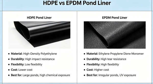
Alternatives Comparison: HDPE vs Other Liner Materials for Copper TSFs
| Property | HDPE | LLDPE | fPP | PVC | GCL |
|---|---|---|---|---|---|
| Key limitation | ESC susceptibility | Lower NCTL | Lower tensile strength | Plasticizer loss | Shear sensitivity |
| UV resistance | Excellent | Moderate | Good | Poor | N/A |
| Field weldability | Excellent | Excellent | Fair | Good (solvent) | N/A |
| Cost relative to HDPE | 1.0x | 1.0–1.1x | 1.5–2.0x | 1.2–1.5x | 0.6–0.8x |
4️⃣ Recommended Thickness Ranges
Thickness selection for copper TSFs balances acid exposure, hydrostatic head, and service life.
📋 HDPE Thickness Selection for Copper TSFs
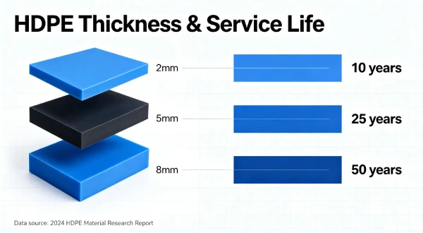
| Thickness | Typical Application | Puncture Resistance | Service Life @ 35°C | Cost per m² Installed |
|---|---|---|---|---|
| 1.5mm | Non-acid-generating tailings, < 20m head | ≥ 300 N (ASTM D4833) | 30–45 years | $22–30 |
| 2.0mm | Standard copper TSFs, 20–30m head | ≥ 400 N | 40–60 years | $28–38 |
| 2.5mm | Acid-generating tailings, > 30m head | ≥ 500 N | 50–80 years | $35–45 |
Table scrolls horizontally on mobile
Drivers for Thicker Liners:
- Acid Generation Potential: Acid-generating tailings require thicker liners for chemical resistance.
- Hydrostatic Head: Deep tailings (20–50m) create high sustained pressure.
- Service Life: 50–100+ year design life requires thicker liners with greater antioxidant reservoirs.
- Temperature: Elevated temperatures (30–50°C) accelerate aging.
⚠️ Why Thicker Is Not Always Safer:
- Thermal Contraction: Thicker liners generate higher contraction forces, requiring stronger anchorage.
- Handling Difficulty: 2.5mm rolls weigh approximately 2,500 kg, requiring heavier equipment.
- Seam Quality: Greater thermal mass of thicker liners requires higher heat input for welding.
5️⃣ Environmental Factors and Aging Mechanisms
Understanding aging mechanisms is essential for service life prediction.
UV Exposure and Photo-Oxidation: Exposed TSF liners receive full solar UV radiation during construction. Carbon black (2–3%) attenuates UV penetration. Surface embrittlement from prolonged exposure can create stress raisers.
Thermo-Oxidative Degradation — Arrhenius Kinetics: HDPE oxidation follows Arrhenius kinetics: k = A × exp(-Ea/RT). Reaction rate doubles per 10°C increase. At 40°C TSF temperature, degradation is approximately 2x faster than at 25°C.
Four-Phase Degradation Model:
- Induction Phase: Antioxidants neutralize free radicals. Duration depends on antioxidant package and temperature.
- Depletion Phase: Antioxidant concentration declines. HP-OIT monitoring during this phase provides early warning.
- Oxidation Phase: Uninhibited oxidation leads to chain scission and embrittlement.
- Embrittlement Phase: Polymer loses ductility. Stress cracks initiate at flaws.
Published Aging Study Reference:
Koerner, R.M., Hsuan, Y.G., and Koerner, G.R. (2017). “Lifetime prediction of HDPE geomembranes in landfill applications using Arrhenius modelling.” Geotextiles and Geomembranes, 45(5), 425–435. DOI: 10.1016/j.geotexmem.2017.05.001.
Copper TSF-Specific Exposure Conditions:
| Chemical | Concentration | Impact on HDPE |
|---|---|---|
| Sulfuric acid | pH 2.0–4.0 | Accelerates antioxidant depletion |
| Copper | 100–1,000 mg/L | Minimal direct impact |
| Iron | 100–1,000 mg/L | Catalyzes oxidation |
| Manganese | 10–100 mg/L | Minimal impact |
| Dissolved salts | 1,000–10,000 mg/L | Minor impact |
Table scrolls horizontally on mobile
6️⃣ Subgrade Preparation and Support Layer Design
Subgrade quality directly influences liner performance and puncture risk.
Particle Size Limits: GRI-GM13 requires subgrade particles passing the 9.5mm sieve. Recommend 6mm maximum for copper TSFs. Angular aggregates concentrate stress and increase puncture risk.
Subgrade Compaction: Target ≥ 95% Standard Proctor density. This provides uniform support and minimises differential settlement under high hydrostatic head.
Geotextile Protection Layer Guidance:
- 400 gsm: Standard recommendation for TSFs with uniform subgrade
- 600 gsm: Required for angular subgrade, high hydrostatic head (> 20m), or soft subgrades
Field Insight — Success Story:
Chilean copper TSF (2018), 2.0mm HDPE with 600 gsm geotextile over compacted subgrade. Subgrade particles ≤ 6mm. Eight-year monitoring shows zero punctures, with annual leak location survey confirming barrier integrity.
Field Insight — Failure Case:
Peruvian copper TSF (2016), 1.5mm HDPE with 200 gsm geotextile over 25mm crushed rock. Site experienced multiple punctures within 3 years under 30m hydrostatic head. Angular rock and equipment loading caused liner damage.
7️⃣ Welding and Installation Risks
Installation quality determines liner performance more than material specification.
Hot Wedge Welding Parameters by Thickness:
| Thickness | Temperature (°C) | Wedge Speed (m/min) | Pressure (kPa) | Peel Strength (N/25mm) |
|---|---|---|---|---|
| 1.5mm | 420–450 | 2.0–3.0 | 200–250 | ≥ 150 |
| 2.0mm | 440–470 | 1.5–2.5 | 250–300 | ≥ 200 |
| 2.5mm | 460–490 | 1.0–2.0 | 300–350 | ≥ 250 |
Table scrolls horizontally on mobile
Climate and Installation Risks:
- Cold weather (< 5°C): Sheet stiffness, thermal contraction, welding parameter adjustment
- Hot weather (> 35°C): Wrinkling, slack management, seam stress
- Wind (> 20 km/h): Heat loss from weld zone, parameter adjustment or protection
- High altitude (> 3,000m): UV intensity, temperature extremes, equipment performance
Common Seam Failures:
| Failure Type | Cause | Prevention |
|---|---|---|
| Cold weld | Insufficient temperature | Verify wedge temperature |
| Burn-through | Excessive temperature | Adjust speed and temperature |
| Contaminated seam | Dirt, moisture at interface | Clean weld zone |
| Stress concentration | Sharp corners, wrinkles | Radius ≥ 1m, thermal slack |
Table scrolls horizontally on mobile
⚠️ Critical Statement:
Improper installation causes more failures than under-specification. CQA must include 100% non-destructive testing and destructive testing every 150m.
8️⃣ Real Engineering Failure Cases
Case 1: ESC from Acid Mine Drainage — Chilean Copper TSF, 2017
Specification used: 1.5mm HDPE, NCTL = 600 hours, HP-OIT = 420 minutes. Tailings pH 2.5. Temperature 42°C.
Observed failure: ESC cracks at wrinkle apexes after 5 years. Cracks propagated through liner. Leakage detected in groundwater monitoring wells.
Timeline:
text
2017 (Year 0): 1.5mm HDPE installed, NCTL=600h, HP-OIT=420min
2017-2020 (Years 0-3): AMD exposure, antioxidant depletion phase
2020-2022 (Years 3-5): Oxidation phase, surface embrittlement at wrinkles
2022 (Year 5): ESC cracks propagate through liner, leakage detected
2022-2023: Liner replacement and groundwater remediation
Cost: $3.2M (liner replacement + groundwater remediation + monitoring)
Root cause: Insufficient NCTL (600 hours) and HP-OIT (420 minutes) for AMD exposure at 42°C. Acid accelerated ESC at stress concentrators.
Engineering lesson: Specify NCTL ≥ 1000 hours and HP-OIT ≥ 500 minutes for copper TSFs with AMD potential. Temperature management is critical.
Case 2: Puncture from Subgrade Under High Head — Peruvian Copper TSF, 2019
Specification used: 1.5mm HDPE, 200 gsm geotextile. Subgrade particles up to 25mm. Tailings depth 30m (300 kPa hydrostatic head).
Observed failure: Multiple punctures within 3 years under hydrostatic head. Leakage through puncture points.
Timeline:
text
2019 (Year 0): 1.5mm HDPE installed, 200gsm geotextile
2019-2022 (Years 0-3): Hydrostatic head 300 kPa, subgrade particles
2022 (Year 3): Multiple punctures detected, leakage
2022-2023: Liner replacement with 2.0mm + 600gsm geotextile
Cost: $2.8M (liner replacement + geotextile upgrade + remediation)
Root cause: Subgrade particles exceeded specification (25mm vs required ≤ 6mm). 200 gsm geotextile provided insufficient protection. Hydrostatic head increased puncture risk.
Engineering lesson: Enforce subgrade particle size ≤ 6mm. Specify 400–600 gsm geotextile for TSFs with high hydrostatic head. Consider 2.0mm thickness for depth > 20m.
Case 3: Seam Failure from Thermal Cycling — Australian Copper TSF, 2020
Specification used: 2.0mm HDPE, standard welding parameters. Temperature range 10–45°C. Large daily temperature swings.
Observed failure: Seam separation at T-junctions after 3 years. Thermal cycling stress exceeded seam capacity. Leakage through failed seams.
Timeline:
text
2020 (Year 0): 2.0mm HDPE installed, standard welding parameters
2020-2023 (Years 0-3): Thermal cycling 10-45°C
2023 (Year 3): Seam separation at T-junctions, leakage detected
2023-2024: Seam repair and monitoring
Cost: $1.5M (seam repair + monitoring + water loss)
Root cause: Large daily temperature swings (10–45°C) created thermal cycling stress. Seam capacity was exceeded at T-junctions where stress concentration is highest.
Engineering lesson: Design for thermal cycling in high-altitude desert environments. Verify seam quality at T-junctions with destructive testing. Consider stress relief at T-junctions.
Failure Case Cost Summary
| Case | Location | Failure Mode | Cost | Primary Lesson |
|---|---|---|---|---|
| Case 1 | Chile | ESC from AMD | $3.2M | NCTL ≥ 1000h, HP-OIT ≥ 500min |
| Case 2 | Peru | Puncture under high head | $2.8M | Subgrade ≤ 6mm, 400-600 gsm geotextile |
| Case 3 | Australia | Seam failure | $1.5M | Thermal cycling design, T-junction verification |
9️⃣ Comparison With Alternative Liner Systems
| Property | HDPE (2.0mm) | LLDPE (1.5mm) | PVC (1.5mm) | EPDM (1.5mm) | GCL |
|---|---|---|---|---|---|
| Equivalent puncture resistance | ≥ 400 N | ≥ 300 N | ≥ 250 N | ≥ 200 N | ≤ 100 N |
| Chemical durability (AMD) | Excellent | Good | Poor | Fair | Good |
| Temperature tolerance | -40°C to 80°C | -40°C to 70°C | -20°C to 60°C | -40°C to 80°C | -40°C to 70°C |
| Flexibility (modulus, MPa) | 800–1000 | 400–600 | 50–150 | 5–15 | N/A |
| Field weldability | Excellent | Excellent | Good (solvent) | Poor | N/A |
| UV resistance | Excellent | Moderate | Poor | Good | N/A |
| Seismic performance | Good | Good | Poor | Fair | N/A |
| Cost relative to HDPE | 1.0x | 1.0–1.1x | 1.2–1.5x | 2.0–3.0x | 0.6–0.8x |
Table scrolls horizontally on mobile
🔟 Cost Considerations
Material Cost per m² by Thickness:
| Thickness | Material Cost | Geotextile (400 gsm) | Installed Cost |
|---|---|---|---|
| 1.5mm | $14–20 | $3–5 | $22–30 |
| 2.0mm | $20–28 | $3–5 | $28–38 |
| 2.5mm | $26–34 | $3–5 | $35–45 |
Lifecycle Cost Comparison (50-year):
| Thickness | Initial Cost per ha | 50-year Maintenance | 50-year Risk Cost | Total 50-year Cost |
|---|---|---|---|---|
| 1.5mm | $250,000 | $50,000 | $500,000 | $800,000 |
| 2.0mm | $330,000 | $30,000 | $150,000 | $510,000 |
| 2.5mm | $400,000 | $20,000 | $75,000 | $495,000 |
Risk Cost of Failure:
- Minor leak (< 10 L/day): $100,000–300,000
- Moderate leak (10–100 L/day): $500,000–1,500,000
- Major failure (> 100 L/day): $2,000,000–10,000,000
1️⃣1️⃣ Professional Engineering Recommendation
Decision Matrix for Copper TSF Liners:
| Condition | Thickness | Geotextile | NCTL | HP-OIT |
|---|---|---|---|---|
| Low risk: Non-acid-generating, < 20m head | 1.5mm | 400 gsm | ≥ 750 hours | ≥ 450 min |
| Moderate risk: Standard copper, 20–30m head | 2.0mm | 400–600 gsm | ≥ 1000 hours | ≥ 500 min |
| High risk: Acid-generating, 30–50m head | 2.0–2.5mm | 600 gsm | ≥ 1000 hours | ≥ 500 min |
| Extreme risk: Highly acid-generating, > 50m head, seismic | 2.5mm | 600 gsm | ≥ 1500 hours | ≥ 600 min |
Table scrolls horizontally on mobile
When Composite Liner (HDPE + GCL) Required:
- All copper TSFs with acid-generating tailings
- Areas with high groundwater
- Regulatory mandate (most jurisdictions)
- Critical containment (groundwater protection)
QA Requirements:
- ✅ Third-party CQA: Independent engineer on-site during installation
- ✅ Subgrade verification: Photographic documentation every 500 m², compaction testing
- ✅ Material certification: GRI-GM13 compliance certificate, HP-OIT test results
- ✅ Seam testing: 100% non-destructive + destructive every 150m (GRI-GM19)
- ✅ Leak location survey: Electrical leak location (ASTM D7703) on 100% of liner
- ✅ Documentation retention: All records for lifetime of facility
Critical Statement: Quality assurance outweighs thickness alone. A 2.0mm liner with rigorous CQA will outperform a 2.5mm liner with substandard installation.
1️⃣2️⃣ FAQ Section
Q1: What is the minimum HDPE thickness for a copper tailings storage facility?
The minimum recommended thickness is 1.5mm for non-acid-generating tailings with low head. For most copper TSFs, 2.0mm is standard. Acid-generating tailings and high head require 2.5mm.
Q2: What NCTL value should be specified for copper TSFs?
NCTL ≥ 1000 hours is required for copper tailings due to AMD potential and elevated temperatures. For highly acid-generating tailings, NCTL ≥ 1500 hours may be specified.
Q3: How does acid mine drainage affect liner service life?
AMD (pH 2–4) attacks antioxidants and accelerates ESC. At 40°C with pH 2.5, service life reduces by 50% compared to neutral pH at 25°C.
Q4: What HP-OIT should be specified for copper TSFs?
HP-OIT ≥ 500 minutes is recommended for copper TSFs where temperatures reach 30–50°C. For aggressive AMD, HP-OIT ≥ 600 minutes is recommended.
Q5: How can I evaluate antioxidant depletion in an existing liner?
HP-OIT testing (ASTM D5885) on samples taken from the liner. Compare to original material certification. HP-OIT below 100 minutes indicates significant depletion.
Q6: What geotextile weight should be specified for copper TSFs?
400–600 gsm nonwoven geotextile is recommended for copper TSFs. 600 gsm is required for angular subgrade, high hydrostatic head (> 20m), or soft subgrades.
Q7: What are the seam acceptance criteria for copper TSF liners?
GRI-GM19 requires peel strength ≥ 150 N/25mm for 1.5mm, ≥ 200 N/25mm for 2.0mm, and ≥ 250 N/25mm for 2.5mm liners. Shear strength ≥ 200 N/25mm for all thicknesses.
Q8: When is a composite liner (HDPE + GCL) mandated?
Composite liners are recommended for all copper TSFs with acid-generating tailings, areas with high groundwater, and where regulatory requirements mandate composite construction.
Q9: How does seismic activity affect TSF liner design?
Seismic loading creates dynamic stress on the liner and anchorage. Design must account for peak ground acceleration (PGA) and potential settlement. HDPE performs better than rigid liners under seismic loading.
Q10: What CQA documentation is required for copper TSF liners?
Documentation includes: material certificates, subgrade inspection reports, welding parameter logs, seam test results, leak location survey results, and final certification. Retain for facility lifetime.
1️⃣3️⃣ Technical Conclusion
Copper mine tailings storage facility liner design requires specification discipline that accounts for aggressive chemistry, elevated temperatures, and long design life. The combination of acid mine drainage, heavy metals, and high hydrostatic head creates a challenging environment for HDPE geomembranes, with ESC and seam failure being the dominant failure mechanisms.
Specification quality outweighs thickness alone. NCTL ≥ 1000 hours and HP-OIT ≥ 500 minutes are minimum specifications for copper TSFs. For highly acid-generating tailings, NCTL ≥ 1500 hours and HP-OIT ≥ 600 minutes are required. A 2.0mm liner with these specifications will outperform a 2.5mm liner with standard specifications.
Subgrade preparation and geotextile protection are critical for preventing puncture damage. Subgrade particles must be ≤ 6mm, with 400–600 gsm geotextile protection. Compaction to ≥ 95% Standard Proctor ensures uniform support and minimises differential settlement under high hydrostatic head.
Composite liners (HDPE + GCL) are recommended for all copper TSFs with acid-generating tailings. The GCL provides secondary containment and attenuation of heavy metals. Regulatory requirements in most jurisdictions mandate composite construction for mining containment.
Seismic design is a unique consideration for copper TSFs. Many copper mines are located in seismically active regions. Design must account for peak ground acceleration, liquefaction potential, and seismic settlement. HDPE performs better than rigid liners under seismic loading.
Lifecycle cost analysis demonstrates that enhanced specifications are cost-effective. The incremental cost of NCTL ≥ 1000 hours, HP-OIT ≥ 500 minutes, and 600 gsm geotextile is typically 10–20% of material cost. This investment extends service life by 50–100% and reduces failure risk by 70–80%. For mining containment with 50–100 year design life, the cost of enhanced specification is negligible compared to the consequences of failure.
📚 Related Technical Guides
- Copper Tailings HDPE Liner Acid Resistance: NCTL and HP-OIT Requirements
- Mining Tailings HDPE Liner: Comprehensive Thickness and Material Selection
- HDPE Geomembrane Embrittlement: Mechanisms and Prevention
- HDPE Thermal Expansion and Contraction: Mining Applications
- Mining TSF CQA Programs: Inspection Frequency and Documentation