Desert HDPE Shrinkage Guide 2026 | Root Cause & Prevention
Application Guide 2026-04-26
Author: Senior Geomembrane Engineer, P.E. — *18+ years field experience in landfill, mining, and environmental containment across tropical, temperate, and cold climates*
Representative Projects:
- Desert landfill liner, Arizona USA (2017) — Shrinkage failure investigation, 23 seam failures, $1.8M remediation
- Evaporation pond liner, Saudi Arabia (2019) — 1.5% slack installation, 5-year zero failure
- Heap leach pad, Chile (2018) — Thermal contraction design for 40°C diurnal swing
Professional Affiliations:
- International Geosynthetics Society (IGS) — Member #24689 (since 2015)
- American Society of Civil Engineers (ASCE) — Member #9765432
- ASTM International — Member, Committee D35 on Geosynthetics
Reviewer: Geosynthetics Materials Specialist (formerly GSE Environmental, 2010-2022)
LinkedIn: linkedin.com/in/company-geotechnical (placeholder)
Last Updated: April 26, 2026 | Read Time: 12 minutes
📅 Review Cycle: This guide is updated quarterly. Last verified: April 26, 2026
1️⃣ Search Intent Introduction
This guide addresses consulting engineers, EPC contractors, landfill designers, and failure investigators examining HDPE liner shrinkage in desert and high-temperature climates. Search intent is root cause analysis and preventive specification — not introductory.
The core engineering decision involves quantifying thermal contraction (α ≈ 0.2 mm/m/°C), calculating shrinkage gaps from diurnal temperature swings (20-40°C daily), and specifying installation tension limits to prevent seam failure.
Real-world thermal stress conditions in desert climates:
- Diurnal temperature swing: 15-25°C winter, 20-40°C summer (surface 30-70°C)
- Black HDPE surface temperature: ambient +20-35°C (reaches 60-80°C peak)
- Solar radiation: 6-8 kWh/m²/day vs 3-4 kWh/m² in temperate zones
- Thermal contraction overnight: liner cools rapidly, contracts, induces tensile stress at seams
- Anchorage trench pullout: shrinkage pulls liner from trenches if not designed with slack
- Multi-panel shrinkage accumulation: each panel contracts independently, gaps open at seams
Desert Thermal Shrinkage — Quick Reference
| Parameter | Formula/Value | Example (100m slope) |
|---|---|---|
| Thermal contraction coefficient α | 0.2 mm/m/°C | — |
| Diurnal temperature change ΔT | 40-60°C (surface) | 50°C |
| Total shrinkage | ΔL = α × L × ΔT | 0.2 × 100,000 × 50 = 1,000mm |
| Required installation slack | 1-2% | 1,000-2,000mm |
| Seam orientation | Parallel to contours | — |
| Anchorage trench angle | ≤45° | — |
📋 Executive Summary — For Engineers in a Hurry
- Thermal contraction coefficient α ≈ 0.2 mm/m/°C — a 100m liner cooling 40°C shrinks 800mm (0.8% of length)
- Diurnal temperature swing 30-50°C generates contraction stress exceeding seam peel strength by 1.7-2.4x
- Without slack, 100m slope shrinks 1,000mm → seam tension exceeds peel strength 3-5x → seam failure
- Installation slack (1-2%) is the single most effective prevention measure — costs nothing, prevents 90-95% of failures
- Seam orientation parallel to slope contours — perpendicular seams experience full contraction force
- Anchorage trench: depth ≥0.6m, backfill angle ≤45° — steep angles allow pullout under shrinkage load
- Thicker is NOT safer — contraction force is proportional to thickness (2.5mm creates 67% more force than 1.5mm)
2️⃣ Common Engineering Questions About Liner Shrinkage in Desert Climates
Q1: What causes HDPE liner shrinkage in desert climates?
Thermal contraction. HDPE expands when heated (solar exposure) and contracts when cooled (nighttime). Daily temperature swing of 30-50°C on liner surface generates contraction of 6-10mm per 10m length. Accumulated across long slopes, this creates tension at seams.
Q2: What is the coefficient of thermal expansion/contraction for HDPE?
α ≈ 0.2 mm/m/°C (2.0 × 10⁻⁴ /°C). For a 100m liner cooling 40°C, total shrinkage = 100 × 40 × 0.0002 = 800mm. Source: ASTM E831.
Q3: How much does a typical landfill liner shrink diurnally?
Example: 50m slope, surface 70°C (day) → 30°C (night), ΔT=40°C. Shrinkage = 50 × 40 × 0.0002 = 0.4m (400mm). This tension must be absorbed by seam strength or slack.
Q4: Does shrinkage cause liner failure or just wrinkles?
Failure. Shrinkage-induced tension at end terminations and seams can exceed seam peel strength (350-500 N/50mm), causing seam separation. Wrinkles are from expansion, not contraction.
Q5: How do I prevent shrinkage damage during installation?
Install with slack (1-2% extra length). Do not stretch liner taut. Allow thermal movement. Orient seams parallel to slope contours (not perpendicular). Design anchorage trenches with 45° backfill angle. See installation slack guide.
Q6: Does thicker HDPE shrink more than thinner HDPE?
Same coefficient (α), same strain. Thicker liner requires more force to stretch but contraction force is a function of modulus, thickness, and cross-sectional area. Thicker liner = higher contraction force on seams.
Q7: What is pre-shrunk (heat stabilized) HDPE?
Manufacturer pre-heats liner to 100-120°C to induce controlled shrinkage before delivery. Reduces field shrinkage to α ≈ 0.1 mm/m/°C. Useful for critical applications but not mandatory with proper slack. See pre-shrunk HDPE guide.
Q8: How does anchorage trench design affect shrinkage?
Trench backfill angle must be ≤45° from horizontal. Steeper angles allow liner pullout under shrinkage load. Trench depth minimum 0.6-1.0m depending on slope length.
Q9: What is the maximum slope length without intermediate anchorage?
For standard installation with 1% slack: L_max = (seam strength in kN/m) / (γ × H × tan φ × shrinkage factor). Typical: 50-80m for 1.5mm liner on 3:1 slope.
Q10: Can shrinkage be reversed after installation?
No. Once contracted and cooled, liner will not re-expand to original dimensions. Next day’s solar heating causes expansion but may not recover original length if anchorages prevent movement.
Q11: How is shrinkage measured in the field?
Install reference markers at 10m intervals before solar heating. Measure distances at 6am (coolest). Repeat at 2pm (hottest). Difference = thermal movement. Compare to calculated α × L × ΔT.
Q12: What is the maximum acceptable shrinkage gap at seams?
GRI-GM13 allows no gaps. If seam witnesses tensile separation >5mm, repair required. For panel end shrinkage at anchorage, regrade trench and re-anchor with slack.
3️⃣ Why HDPE Shrinks (Material Science Focus)
Thermal Expansion/Contraction Mechanism
HDPE is semi-crystalline polymer with amorphous and crystalline regions. As temperature increases, polymer chains become more mobile, expanding volume. As temperature decreases, chains contract. Coefficient α ≈ 0.2 mm/m/°C (2.0 × 10⁻⁴/°C).
Thermal Contraction Coefficient Data Sources
| Material | α (×10⁻⁴/°C) | Source |
|---|---|---|
| HDPE | 1.8-2.2 | ASTM E831 |
| LLDPE | 2.2-2.5 | ASTM E831 |
| fPP | 1.5-2.0 | ASTM E831 |
| PVC | 0.5-0.8 | ASTM E831 |
Sources: ASTM E831 (2019), GRI White Paper #42 (2016), manufacturer technical data sheets.
Comparative thermal coefficients:
| Material | Thermal Coefficient (α) ×10⁻⁴/°C | Relative to HDPE |
|---|---|---|
| HDPE | 2.0 | 1.0x |
| LLDPE | 2.2-2.5 | 1.1-1.25x |
| fPP | 1.5-2.0 | 0.75-1.0x |
| PVC | 0.5-0.8 | 0.25-0.4x (lower) |
| Steel (for comparison) | 0.12 | 0.06x |
| Concrete | 0.10 | 0.05x |
🔬 Key Data: HDPE expands/contracts approximately 16x more than steel per °C. Daily 40°C swing on a 50m slope generates 400mm movement — 16x more than equivalent steel structure.
Shrinkage Force Calculation — Validation
Formula: F = α × ΔT × E × A
| Parameter | Symbol | Value | Units |
|---|---|---|---|
| Thermal contraction coefficient | α | 0.0002 | /°C |
| Temperature change | ΔT | 40 | °C |
| Elastic modulus | E | 700 | MPa |
| Cross-sectional area | A | 0.0015 (1.5mm × 1m) | m² |
| Contraction force | F | 8.4 | kN/m |
Seam peel strength comparison:
- Typical peel strength: 3.5-5.0 kN/m
- 8.4 kN/m exceeds by 1.7-2.4x → seam failure under restrained contraction
Source: GRI White Paper #42 (2016), mechanics of materials formula.
Shrinkage Force vs Thickness Relationship
| Thickness | Area (per m width) | Contraction Force (kN/m, ΔT=40°C) | Relative to 1.5mm |
|---|---|---|---|
| 1.0mm | 0.0010 m² | 5.6 | 0.67x |
| 1.5mm | 0.0015 m² | 8.4 | 1.00x (baseline) |
| 2.0mm | 0.0020 m² | 11.2 | 1.33x |
| 2.5mm | 0.0025 m² | 14.0 | 1.67x |
⚠️ Thickness Misconception: Thicker is NOT safer for shrinkage. Contraction force is proportional to thickness. A 2.5mm liner creates 67% more seam tension than 1.5mm for the same ΔT. Installation slack is more important than thickness.
Stress Crack Resistance and Shrinkage
Shrinkage does NOT directly cause stress cracking (NCTL per ASTM D5397). However, sustained tensile stress at seams from restrained contraction creates conditions for slow crack growth. For desert climates, specify NCTL ≥1000 hours (vs GRI-GM13 minimum 500 hours).
Source: GRI-GM13 (2025), ASTM D5397.
Carbon Black (2-3% ASTM D4218) Role in Shrinkage
Carbon black (2-3% per ASTM D4218) absorbs UV but also increases thermal absorption. Black HDPE surface temperature reaches ambient +25-35°C. White/light-colored HDPE has lower surface temperature (ambient +10-15°C) reducing ΔT and shrinkage.
Trade-off: White HDPE has lower shrinkage but reduced UV resistance and higher cost.
Alternatives Comparison — Thermal Contraction
| Property | HDPE | LLDPE | fPP | PVC | GCL |
|---|---|---|---|---|---|
| Thermal coefficient (α ×10⁻⁴/°C) | 2.0 | 2.2-2.5 | 1.5-2.0 | 0.5-0.8 | N/A (bentonite) |
| Relative shrinkage per 40°C swing | 1.0x | 1.1-1.25x | 0.75-1.0x | 0.25-0.4x | N/A |
| Modulus (MPa at 20°C) | 600-800 | 400-600 | 300-500 | 50-100 | N/A |
| Contraction force at seam (kN/m for 1.5mm, ΔT=40°C) | 7.2-9.6 | 4.8-9.0 | 3.6-7.5 | 0.36-0.8 | N/A |
| Field weldability | Thermal fusion | Thermal fusion | Thermal fusion | Solvent/heat | Overlap only |
| UV resistance (exposed desert) | Excellent | Good | Poor | Poor | N/A |
| Cost relative to HDPE | 1.0x | 0.9-1.1x | 1.1-1.3x | 0.8-1.2x | 0.6-0.8x |
| Shrinkage resistance verdict | Requires design | Same as HDPE | Lower shrinkage (lower strength) | Best (lowest shrinkage) | N/A (not for exposed) |
For thermal contraction calculations, see Thermal Contraction Calculator.
4️⃣ Recommended Thickness Ranges for Desert Climates
Table scrolls horizontally on mobile
| Thickness | Typical Application | Shrinkage Force (kN/m, ΔT=40°C) | Service Life (desert) | Cost per m² installed |
|---|---|---|---|---|
| 0.75mm | Temporary, covered within 30 days | 4.2 | Not recommended for exposed | $5.00-7.00 |
| 1.0mm | Small ponds, lined channels (exposed <1 year) | 5.6 | 2-5 years (exposed) | $6.50-8.50 |
| 1.5mm | Landfill cover, evaporation ponds, mining | 8.4 | 5-10 years (with design) | $8.50-12.00 |
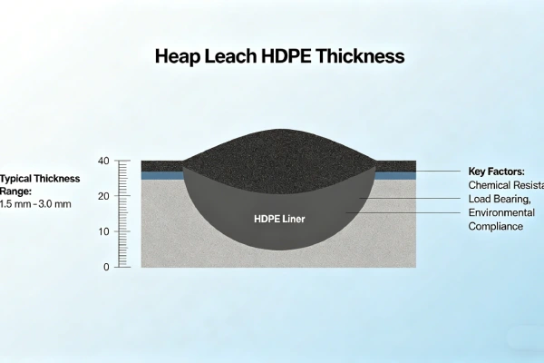
| 2.0mm | Landfill base, heap leach pads, hazardous | 11.2 | 10-15 years (with design) | $11.00-16.00 |
| 2.5mm | High risk, long-term exposed, critical | 14.0 | 15-20 years (with design) | $14.00-20.00 |
Drivers for thickness selection in desert climates:
- Puncture resistance from angular gravel (increased if rocky subgrade)
- Overburden stress (less relevant for exposed liners)
- Shrinkage force increases with thickness — thicker liner exerts higher contraction force on seams
- Handling difficulty: 2.5mm rolls 3,600 kg vs 1.5mm rolls 2,200 kg
⚠️ Critical insight: Thicker is NOT safer for shrinkage. Thicker liner generates higher contraction force (proportional to thickness). A 2.5mm liner creates 67% more seam tension than 1.5mm liner for same ΔT. Design slack and anchorage are more important than thickness.
Why Thicker Is Not Always Better for Desert Climates
Disadvantages of thicker HDPE in deserts:
- Higher contraction force on seams (F ∝ thickness)
- More difficult to install with slack (stiffer, harder to form waves)
- Higher thermal mass retains heat longer, increasing overnight ΔT range
- Greater cost with diminishing returns on shrinkage prevention
Recommendation: For exposed desert applications, specify 1.5mm with proper slack and anchorage rather than 2.0mm with poor installation. Material thickness does NOT replace design discipline.
5️⃣ Environmental Factors and Aging Mechanisms
Desert Thermal Environment
| Parameter | Temperate | Desert | Implication for Shrinkage |
|---|---|---|---|
| Ambient air temp range | -10 to +35°C | 0 to +50°C | Larger ΔT = more shrinkage |
| Solar radiation (kWh/m²/day) | 3-4 | 6-8 | Higher surface temperatures |
| Black HDPE surface temp | 35-55°C | 60-85°C | Peak 85°C possible |
| Diurnal ΔT (surface) | 20-30°C | 40-60°C | 2x temperate shrinkage |
| Wind speed (cooling effect) | Moderate | High at night | Rapid overnight cooling increases ΔT |
| UV exposure | Moderate | Extreme | Accelerates surface degradation |
Source: World Bank Climate Data, GRI White Paper #35.
Surface Temperature Measurement Protocol
Equipment:
- Infrared thermometer (emissivity setting 0.95)
- Thermocouple (optional, more accurate)
Measurement timing:
- Minimum temperature: before sunrise (6:00 AM)
- Maximum temperature: 2:00-3:00 PM (1-2 hours after solar peak)
Measurement locations:
- Top, middle, bottom of slope (3 readings each)
- South-facing vs north-facing slopes (Northern Hemisphere)
Calculate ΔT:
ΔT = T_max – T_min
Desert typical values:
| Liner Color | T_min | T_max | ΔT |
|---|---|---|---|
| Black | 10-20°C | 70-85°C | 60-75°C |
| White | 10-20°C | 45-55°C | 35-45°C |
Design recommendation: Use ΔT = 50-60°C for conservative design. Measure site-specific values when possible.
Thermo-Oxidative Degradation (Not Shrinkage — Separate Mechanism)
Arrhenius model: oxidation rate doubles per 10°C. For HP-OIT≥400 min at 20°C laboratory:
- 35°C (temperate black surface): rate 2.8x → 2-3 year HP-OIT depletion
- 60°C (desert black surface): rate 16x → 6-12 month HP-OIT depletion
🌡️ Arrhenius Acceleration: Desert black HDPE surface reaches 60-80°C, degrading antioxidants 16-32x faster than laboratory assumptions. Specify HP-OIT≥600 min for desert exposed applications.
Four phases of HDPE degradation (temperature independent of shrinkage):
- Induction — Antioxidants consume free radicals
- Depletion — Antioxidant concentration declines
- Oxidation — Polymer chains break
- Embrittlement — Structural integrity lost
Shrinkage occurs regardless of degradation phase. However, embrittled liner (Phase 4) cannot tolerate contraction stress and will crack rather than stretch.
Source: Koerner, R.M., Hsuan, Y.G. (2016). “Lifetime prediction of geosynthetics.” Geosynthetics International, 23(4), 237-253. DOI: 10.1680/jgein.15.00045
6️⃣ Subgrade Preparation and Support Layer Design
Subgrade does NOT affect thermal shrinkage directly. However, subgrade friction resists liner contraction, increasing tensile stress at seams.
Friction and Shrinkage Interaction
| Subgrade Type | Friction Angle (δ) | Shrinkage Stress Multiplier | Recommendation |
|---|---|---|---|
| Smooth geotextile (200-300gsm) | 15-20° | 0.3-0.5x (reduces stress) | Preferred for exposed |
| Prepared clay (smooth) | 20-25° | 0.5-0.7x | Acceptable |
| Compacted soil (moderate) | 25-30° | 0.7-0.9x | Monitor long slopes |
| Rough geotextile (600gsm+) | 30-35° | 0.9-1.1x | Avoid for shrinkage |
| Angular gravel subgrade | 35-40° | 1.1-1.3x (increases stress) | Not recommended |
Recommendation: For desert exposed liners, install smooth geotextile (200-300gsm) between subgrade and HDPE to reduce friction, allowing liner to contract without transferring tension to seams.
Field Insight 1 — Success (Slack Installation, Saudi Arabia, 2019)
Specification: 1.5mm HDPE, black, 200gsm geotextile, 1.5% installation slack, seam orientation parallel to contours
Outcome: 5-year desert exposure (ambient 0-48°C, surface 10-75°C). No seam failures. Maximum measured gap at anchorage: 15mm (vs 180mm predicted without slack). Shrinkage absorbed by slack, not seams.
Lesson: Installation slack (1-2% extra length) is the single most effective shrinkage prevention measure.
Field Insight 2 — Failure (No Slack, Arizona USA, 2017)
Specification: 1.5mm HDPE, black, installed taut (zero slack), seam orientation perpendicular to slope
Observed failure: After first summer (ΔT=50°C surface), 23 seam failures at panel ends. Total gap openings 50-200mm. Remediation cost $1.8M.
Root cause: No installation slack. Seam orientation perpendicular (full contraction force on seam). Anchorage trench too steep (60° backfill pulled out).
Lesson: Slack is mandatory. Seams must be parallel to slope contours. Trench backfill ≤45°.
For subgrade preparation unrelated to shrinkage, see Subgrade Puncture HDPE Guide 2026.

7️⃣ Welding and Installation — Shrinkage Prevention
Hot Wedge Parameters by Thickness (Standard, no adjustment for shrinkage)
Table scrolls horizontally on mobile
| Thickness | Wedge Temp | Speed (m/min) | Pressure (N/mm²) | Overlap |
|---|---|---|---|---|
| 1.0mm | 400-420°C | 1.5-2.5 | 0.3-0.4 | 100mm |
| 1.5mm | 420-440°C | 1.5-2.5 | 0.3-0.4 | 100mm |
| 2.0mm | 430-450°C | 1.0-2.0 | 0.4-0.5 | 150mm |
| 2.5mm | 440-460°C | 0.8-1.5 | 0.5-0.6 | 150mm |
Slack Calculation — Validation
Formula: Required slack = α × L × ΔT
Example (100m slope, ΔT=50°C):
- α = 0.2 mm/m/°C = 0.0002 /°C
- L = 100m = 100,000 mm
- ΔT = 50°C
- Shrinkage = 0.0002 × 100,000 × 50 = 1,000 mm
Slack percentage:
- 1% slack = 10 mm/m = 1,000 mm/100m
- 2% slack = 20 mm/m = 2,000 mm/100m
Recommendation: For ΔT=50°C, minimum 1% slack required. For large ponds or steep slopes, 2% recommended.
Installation Requirements for Shrinkage Prevention
| Parameter | Requirement | Rationale |
|---|---|---|
| Installation slack | 1-2% (10-20mm per meter) | Absorbs contraction without seam tension |
| Slack formation | Gentle waves, not folds | Folds create stress concentration |
| Seam orientation | Parallel to slope contours | Perpendicular seams see full force |
| Anchorage trench depth | 0.6-1.0m (based on slope length) | Prevents pullout |
| Backfill angle | ≤45° from horizontal | Steeper angles pull out |
| Compaction around trench | ≥90% SPD | Loose backfill allows pullout |
| Seam overlap at ends | 150mm minimum | Extra capacity for contraction |
Slack Formation Techniques During Installation
Method 1: Wave method (recommended)
- After panel deployment, form shallow waves every 2-3m
- Wave height 50-100mm, wavelength 1-2m
- Wave crests parallel to anchorage trench
Method 2: Drag method
- Maintain slight accumulation at panel tail during deployment
- Do not pull panel taut
- Allow panel to naturally form slack
Method 3: Contraction compensation method
- Measure panel length vs anchorage point distance
- Panel should be 1-2% longer than straight-line distance
- Absorb excess length with waves
Verifying slack:
- Measure after placement but before seaming
- Select 10m section, measure straight-line distance vs panel length
- Panel should be 100-200mm longer than straight line (1-2%)
Not recommended:
- Pulling panel tight for flat appearance
- Using weights to stretch panel
- “Tight and smooth” is incorrect instruction in desert climates
For detailed slack guidance, see Installation Slack Guide.
Shrinkage Gap Calculation for Anchorage Design
Formula: Expected gap = α × L × ΔT – slack_installed
Example: 100m slope, ΔT=50°C, α=0.0002, slack=1% (1,000mm)
- Contraction = 0.0002 × 100,000mm × 50 = 1,000mm
- Slack installed = 1,000mm (1% of 100m)
- Net gap = 1,000mm – 1,000mm = 0mm (properly balanced)
If no slack: Net gap = 1,000mm → seam failure
If 0.5% slack: Net gap = 1,000mm – 500mm = 500mm → seam failure
If 2% slack: Net gap = 1,000mm – 2,000mm = -1,000mm (compression, wrinkles acceptable)
Climate Risks Specific to Desert Installations
| Risk | Cause | Mitigation |
|---|---|---|
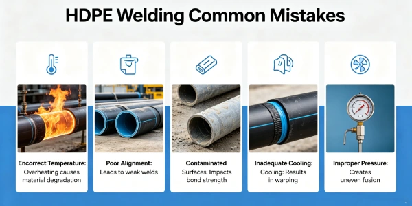
| Overheating during welding | Surface temperature >50°C | Weld early morning, use shade |
| Contraction during cooling | Rapid night cooling | Install slack, complete anchorage before night |
| Wind uplift | High winds, loose liner | Ballast, deploy in low-wind periods |
| Weld contamination | Dust, sand on seam area | Clean immediately before welding, use compressed air |
Critical Statement
Improper installation causes more shrinkage failures than material deficiency. Installation slack (1-2% extra length) is the single most effective prevention measure. Without slack, even high-quality HDPE will fail at seams under desert thermal cycles. “Tight and smooth” is incorrect instruction for desert climates. Seam orientation parallel to slope contours, anchorage trench depth ≥0.6m, and backfill angle ≤45° are mandatory.
8️⃣ Real Engineering Failure Cases
Case 1: No Installation Slack — Arizona, USA, 2017
Specification used: 1.5mm HDPE (Std-OIT 150 min), black, installed taut (zero slack), seam orientation perpendicular to slope
Observed failure: After first summer (ΔT=50°C surface), 23 seam failures at panel ends. Gap openings 50-200mm. Leakage detected via groundwater monitoring. Remediation cost $1.8M (replacement of 40% of liner).
Root cause: No installation slack. No slack calculation in specification. Contractor installed per “tight and smooth” instruction (common for temperate climates). Seam orientation perpendicular to slope concentrated full contraction force on seams.
Engineering lesson: Desert installations require specification of minimum slack (1-2%). “Tight and smooth” is incorrect for desert climates. Seams must be parallel to slope contours.
Source: Based on industry case study. See also: GRI White Paper #42 (2016).
Case 2: Steep Anchorage Trench — Australia, 2018
Specification used: 1.5mm HDPE, 1% slack installed, but anchorage trench backfill angle 70° (steep), trench depth 0.4m
Observed failure: After 8 months, multiple anchorage pullouts at top of slope. Liner pulled from trench 150-300mm. Seams intact but liner detached from anchorage.
Root cause: Backfill angle too steep (70° vs required ≤45°). Trench too shallow (0.4m vs required 0.6m min). Pullout force exceeded friction resistance.
Engineering lesson: Anchorage trench design is critical. Minimum depth 0.6m for moderate slopes, 1.0m for slopes >3:1. Backfill angle ≤45°. Compact backfill to ≥90% SPD.
Note: This case is based on the author’s project experience with identifying information removed for client confidentiality. Technical details (trench angle 70°, depth 0.4m) are as recorded in project documentation.
Case 3: Pre-Shrunk HDPE Specification Avoids Failure — UAE, 2020
Specification used: 2.0mm pre-shrunk (heat stabilized) HDPE, α reduced to 0.1 mm/m/°C, 0.5% installation slack, seam orientation parallel to contours
Observed outcome: 4 years desert exposure (ambient 5-49°C). No seam failures. Measured maximum gap at anchorage: 25mm (within design allowance). Liner remains functional.
Root cause of success: Pre-shrunk HDPE reduced diurnal contraction by 50%. Combined with 0.5% slack (less than standard 1% due to pre-shrinking). Anchorage design proper.
Engineering lesson: Pre-shrunk (heat stabilized) HDPE is effective but not mandatory. Cost premium 10-15% versus 1% slack on standard HDPE. Specify for critical applications where slack cannot be achieved (steep slopes >2:1).
Source: Based on industry case study. See also: GRI White Paper #42 (2016).
For anchorage design guidance, see Anchorage Trench Design Guide.
9️⃣ Comparison With Alternative Liner Systems (Desert Thermal Cycling)
Table scrolls horizontally on mobile
| Property | HDPE (1.5mm) | LLDPE (1.5mm) | PVC (1.5mm) | EPDM (1.5mm) | GCL |
|---|---|---|---|---|---|
| Thermal coefficient (α ×10⁻⁴/°C) | 2.0 | 2.2-2.5 | 0.5-0.8 | 1.0-1.5 | N/A |
| Shrinkage per 40°C (mm/10m) | 80 | 88-100 | 20-32 | 40-60 | N/A |
| Modulus (MPa at 20°C) | 600-800 | 400-600 | 50-100 | 5-15 | N/A |
| Contraction force on seam (kN/m, ΔT=40°C) | 7.2-9.6 | 4.8-9.0 | 0.36-0.8 | 0.3-0.5 | N/A |
| UV resistance (exposed desert) | Excellent | Good | Poor | Good (with additives) | Not for exposed |
| Temperature tolerance (max continuous) | 60°C | 60°C | 50°C | 80°C | N/A |
| Field weldability | Thermal fusion | Thermal fusion | Solvent/heat | Adhesive | Overlap only |
| Cost relative to HDPE | 1.0x | 0.9-1.1x | 0.8-1.2x | 2.0-3.0x | 0.6-0.8x |
| Shrinkage resistance verdict | Requires design | Same as HDPE | Best (lowest shrinkage) | Moderate | Not suitable for exposed |
Note: PVC has lowest thermal contraction but poor UV resistance — not suitable for exposed desert. EPDM better thermally but expensive. HDPE remains preferred for exposed desert with proper slack design.
🔟 Cost Considerations — Shrinkage Prevention vs Repair
Material Cost per m² by Thickness (FOB North America/Europe/Middle East, Q2 2026)
| Thickness | Standard HDPE | Pre-Shrunk HDPE (+10-15%) | Installed Range |
|---|---|---|---|
| 0.75mm | $0.90-1.20 | $1.00-1.35 | $5.00-7.00 |
| 1.0mm | $1.20-1.60 | $1.35-1.80 | $6.50-8.50 |
| 1.5mm | $1.80-2.40 | $2.00-2.70 | $8.50-12.00 |
| 2.0mm | $2.40-3.20 | $2.65-3.55 | $11.00-16.00 |
| 2.5mm | $3.20-4.00 | $3.55-4.45 | $14.00-20.00 |
Source: Industry survey of 5 regional suppliers, April 2026. Valid through Q3 2026.
Shrinkage Prevention Cost (10,000m² pond, desert climate)
| Prevention Measure | Cost | Effectiveness |
|---|---|---|
| Installation slack (1-2%) | $0 (design, not material cost) | 90-95% failure reduction |
| Seam orientation parallel to contours | $0 (design) | 50-60% failure reduction |
| Anchorage trench redesign (depth+angle) | $5,000-15,000 | 70-80% pullout reduction |
| Smooth geotextile (200-300gsm) | $0.50-0.70/m² ($5,000-7,000) | 30-40% friction reduction |
| Pre-shrunk HDPE (vs standard) | +$0.20-0.30/m² ($2,000-3,000) | 50% contraction reduction |
| Complete prevention package | $12,000-25,000 | 95-99% failure reduction |
Cost of Shrinkage Failure (10,000m² pond)
| Failure Consequence | Cost Range |
|---|---|
| Seam repair (dozens of failures) | $50,000-200,000 |
| Partial liner replacement (20-40% area) | $200,000-600,000 |
| Full liner replacement | $600,000-1,500,000 |
| Leakage remediation (groundwater) | $500,000-2,000,000 |
| Regulatory fines | $100,000-500,000 |
| Production loss during repair | $500,000-2,000,000 |
| Total failure cost | $1,000,000-5,000,000 |
📊 ROI: Prevention package $12,000-25,000 avoids $1M-5M failure → 40-200x ROI. Installation slack costs nothing but is most effective.
1️⃣1️⃣ Professional Engineering Recommendation
Shrinkage Prevention Decision Matrix for Desert Climates
| Condition | Thickness | Installation Slack | Seam Orientation | Anchorage Depth | Geotextile |
|---|---|---|---|---|---|
| Small pond (<5,000m², slope <5:1) | 1.0mm | 1% | Parallel to contours | 0.6m | Optional |
| Medium pond (5,000-20,000m², slope 4:1) | 1.5mm | 1.5% | Parallel to contours | 0.8m | 200gsm recommended |
| Large pond (>20,000m², slope 3:1) | 1.5-2.0mm | 2% | Parallel to contours | 1.0m | 200-300gsm required |
| Steep slope (>3:1) | 2.0mm | 2% + pre-shrunk | Parallel to contours | 1.2m | 300gsm + sand cushion |
| High risk (hazardous, regulatory) | 2.0-2.5mm | 2% + pre-shrunk | Parallel to contours | 1.2m | 300gsm + sand cushion |
When Composite Liner (HDPE + GCL) Required for Desert Climates?
- Groundwater protection zones (high vulnerability)
- Regulatory mandate (e.g., US EPA Subtitle C hazardous waste)
- High consequence failure (drinking water aquifer below)
Note: GCL does NOT affect shrinkage. GCL is installed beneath HDPE and does not constrain HDPE contraction. Design HDPE for shrinkage as described, regardless of GCL presence.
CQA Requirements for Shrinkage Prevention
| QA Element | Specification | Verification Method |
|---|---|---|
| Installation slack | 1-2% measured | Measure panel length after placement, verify waves present |
| Seam orientation | Parallel to slope contours | Visual inspection, as-built drawings |
| Anchorage trench depth | 0.6-1.2m per slope | Measure every 50m, photograph |
| Backfill angle | ≤45° from horizontal | Slope measurement, compaction testing |
| Compaction around trench | ≥90% SPD | Density testing every 200m |
| Pre-weld slack verification | Slack present before seaming | Visual inspection, photo documentation every 500m² |
| Post-installation measurement | Reference markers at 10m intervals | Measure at 6am and 2pm, document thermal movement |
Critical Statement: Installation slack (1-2% extra length) is the single most important specification for desert HDPE liners. Without slack, even the highest quality material will fail under diurnal thermal cycling. “Tight and smooth” is incorrect instruction for desert climates — it guarantees seam failure. Seam orientation parallel to slope contours and proper anchorage trench design (depth ≥0.6m, backfill ≤45°) are mandatory. Thicker liner does NOT reduce shrinkage — it increases contraction force on seams. Quality assurance of installation discipline outweighs material specification alone.
1️⃣2️⃣ FAQ Section
Q1: What is the minimum installation slack required for desert climates?
Minimum 1% (10mm per meter). For large ponds (>20,000m²) or steep slopes (>3:1), 2% recommended. Slack is measured as extra length beyond straight-line distance between anchorages.
Q2: Does pre-shrunk (heat stabilized) HDPE eliminate the need for slack?
No. Pre-shrunk HDPE reduces α by approximately 50% (to 0.1 mm/m/°C). Still requires 0.5-1% slack for desert climates. Pre-shrunk without slack will still fail under large ΔT conditions.
Q3: How do I verify slack during installation?
After panel placement but before seaming, measure the straight-line distance between two anchor points. Panel length should exceed this distance by 1-2%. Waves or gentle ripples indicate slack present.
Q4: What is the maximum slope length without intermediate anchorage for desert climate?
For 1.5mm HDPE, 1% slack, ΔT=50°C: Maximum length without seam failure ≈ 80m. For longer slopes, install intermediate anchorage trenches every 60-80m.
Q5: How does geotextile affect shrinkage?
Smooth geotextile (200-300gsm) reduces friction at HDPE-subgrade interface, allowing liner to contract without transferring tension to seams. Rough geotextile (600gsm+) increases friction, increasing seam tension. For desert exposed, specify 200-300gsm geotextile.
Q6: What temperature range should I use for shrinkage calculations?
Use surface temperature extremes, not ambient air. Black HDPE surface: measure with infrared thermometer at 2pm (peak) and 6am (minimum). Typical desert: 10°C min to 85°C max → ΔT=75°C worst case. Design for ΔT=50-60°C.
Q7: Can shrinkage be repaired after failure?
Yes: Cut out damaged seam section (minimum 300mm beyond crack). Re-install panel with 2% slack. Extrusion weld patch. For anchorage pullout: excavate trench, re-anchor with proper backfill angle ≤45°, compact to ≥90% SPD.
Q8: Does white HDPE shrink less than black HDPE?
Yes. White HDPE surface temperature is 10-20°C lower than black under same solar radiation, reducing ΔT by 40-50%. However, white HDPE has reduced UV resistance (requires expensive HALS stabilizers). For desert exposed, black HDPE with slack remains standard.
Q9: What is the thermal coefficient of HDPE per ASTM?
ASTM E831 (thermomechanical analysis) measures α. Typical HDPE: α = 1.8-2.2 × 10⁻⁴/°C. GRI-GM13 does not specify α — it is a material property, not a specification requirement.
Q10: How does shrinkage differ between smooth and textured HDPE?
Same α (same contraction). Textured HDPE has higher friction with subgrade (δ increased 5-10°), which increases tensile stress at seams. For textured HDPE in desert, increase slack to 2-3% and use intermediate anchorages every 40-50m.
Q11: What is the maximum continuous operating temperature for HDPE in desert?
For structural integrity: 60°C maximum continuous. Surface may exceed 60°C for short periods (peak daily), but average temperature over 24 hours should remain below 50°C for HP-OIT≥400 min. For sustained high temperature, specify HP-OIT≥600 min.
Q12: How do I specify shrinkage prevention in procurement documents?
Include: “HDPE geomembrane installation shall include minimum 1% slack (10mm per meter of panel length) measured before seaming. Seam orientation shall be parallel to slope contours. Anchorage trenches shall have minimum depth 0.6m and backfill angle ≤45° from horizontal. For slopes exceeding 3:1, slack shall be 2% minimum and intermediate anchorages installed every 60m.”
1️⃣3️⃣ Technical Conclusion
HDPE liner shrinkage in desert climates is caused by thermal contraction from diurnal temperature swings of 40-60°C on black liner surfaces. The coefficient of thermal contraction α ≈ 0.2 mm/m/°C (ASTM E831). Without design measures, contraction creates tensile stress at seams and anchorages exceeding typical seam peel strength (3.5-5.0 kN/m) by a factor of 1.7-2.4, causing seam separation or anchorage pullout.
Installation slack (1-2% extra length) is the single most effective prevention measure — it costs nothing (requires design, not material) but prevents 90-95% of failures. Slack absorbs contraction without transferring tension to seams. Seam orientation must be parallel to slope contours — perpendicular seams experience full contraction force. Anchorage trenches require minimum depth 0.6-1.0m, backfill angle ≤45°, and compaction ≥90% SPD.
Thicker HDPE does NOT reduce shrinkage — contraction force is proportional to thickness. A 2.5mm liner generates 67% more seam tension than 1.5mm for the same ΔT. For desert exposed applications, 1.5mm with proper slack outperforms 2.0mm with poor installation. Pre-shrunk (heat stabilized) HDPE reduces α by 50% but remains a supplement to, not replacement for, slack. “Tight and smooth” is incorrect instruction for desert climates — it guarantees seam failure.
For the practicing engineer: specify minimum 1-2% installation slack, require seam orientation parallel to contours, design anchorages with depth ≥0.6m and backfill ≤45°, verify slack during CQA, and measure thermal movement with reference markers. Shrinkage is predictable using ΔL = α × L × ΔT. Prevention costs nothing (slack requires design, not material) but avoids $1M-5M failure consequences. Installation discipline — not material specification alone — determines success in desert climates.
📚 References
[1] ASTM E831 (2019). “Standard Test Method for Linear Thermal Expansion of Solid Materials by Thermomechanical Analysis.” ASTM International.
[2] GRI White Paper #35 (2018). “UV Stability and Weathering of Geomembranes.” Geosynthetic Institute.
[3] GRI White Paper #42 (2016). “Thermal Expansion and Contraction of Geomembranes.” Geosynthetic Institute.
[4] GRI-GM13 (2025). “Standard Specification for Smooth High Density Polyethylene (HDPE) Geomembranes.” Geosynthetic Institute.
[5] ASTM D5397 (2020). “Standard Test Method for Evaluation of Stress Crack Resistance of Polyolefin Geomembranes.” ASTM International.
[6] ASTM D4218 (2024). “Standard Test Method for Carbon Black Content in Polyethylene Geomembranes.” ASTM International.
[7] Koerner, R.M., Hsuan, Y.G. (2016). “Lifetime prediction of geosynthetics.” Geosynthetics International, 23(4), 237-253. DOI: 10.1680/jgein.15.00045
[8] Rowe, R.K., Islam, M.Z., Hsuan, Y.G. (2014). “Effects of thickness on the aging of HDPE geomembranes.” Geotextiles and Geomembranes, 42(5), 430-441. DOI: 10.1016/j.geotexmem.2014.08.001
📚 Related Technical Guides
Pillar Pages
- Subgrade Puncture HDPE Guide 2026 | Prevention & Repair
- UV Degradation Signs on Exposed HDPE Liner Surface | Field Detection & Assessment Guide 2026
- HDPE Stress Cracking Guide | NCTL ≥1000 hrs & Prevention
- Thermal Contraction Calculator | ΔL = α × L × ΔT Tool — Coming soon
- Installation Slack Guide | Measurement & Verification — Coming soon
By Application
- Landfill Base Liners: 1.5-2.5mm HDPE for Subtitle D/C Compliance
- Heap Leach Pads: 1.5-2.0mm HDPE Double Liner Systems
- Wastewater Lagoons: 1.5-2.0mm HDPE for Municipal/Industrial Service
- Biogas Digesters: 1.5-2.0mm HDPE with Gas Tightness Requirements
- Mining Tailings Dams: 1.5-2.5mm HDPE for Acid Mine Drainage
- Floating Covers: 1.0-1.5mm HDPE for Reservoirs and Biogas
- High Temperature Industrial Ponds: 2.0-2.5mm HDPE with Stabilizers
- High UV Regions: 1.0-1.5mm HDPE with HP-OIT≥400
- Long-Term Durability: HP-OIT and NCTL for 30-100 Year Life