HDPE Oxidation in Exposed Applications Guide 2026 | Causes & Prevention
Application Guide 2026-07-01
Author: Senior Geomembrane Engineer, P.E. — 15+ years field experience in exposed geomembrane applications including heap leach pads, wastewater lagoons, mining tailings ponds, and landfill caps across tropical, temperate, and arid climates
Reviewer: Geosynthetics Materials Specialist
Last Updated: June 27, 2026
Read Time: 12 minutes
📅 Review Cycle: This guide is updated quarterly. Last verified: June 27, 2026
📋 Executive Summary — For Engineers in a Hurry
- UV radiation is the primary oxidation driver in exposed applications, causing photo-oxidation confined to the surface 0.1–0.3mm layer
- Carbon black (2–3%) is the primary UV protectant — proper dispersion (ASTM D5596 rating ≥ 1) is critical for protection effectiveness
- Surface temperature in direct sunlight can reach 60–80°C, accelerating thermo-oxidative degradation by 4–16x compared to 20°C
- HP-OIT monitoring of surface samples detects oxidation before visible degradation appears — values below 200 minutes require investigation
- Protection strategies include carbon black specification, UV-stabilised resins, sacrificial surface layers, and minimising exposure duration
- Field welding of oxidized surfaces is unreliable — surface scraping may be required for weld quality
📑 Table of Contents
1️⃣ Search Intent Introduction
2️⃣ Common Engineering Questions About HDPE Oxidation in Exposed Applications
3️⃣ Why HDPE Is Used — Material Science Focus
4️⃣ UV Radiation and Photo-Oxidation Mechanisms
5️⃣ Thermo-Oxidative Degradation in Exposed Conditions
6️⃣ Carbon Black Protection — Specification and Performance
7️⃣ Combined Degradation Mechanisms — UV + Heat + Stress
8️⃣ Real Engineering Failure Cases
9️⃣ Comparison With Alternative Liner Systems for Exposed Applications
🔟 Prevention Strategies and Monitoring
1️⃣1️⃣ Professional Engineering Recommendation
1️⃣2️⃣ FAQ Section
1️⃣3️⃣ Technical Conclusion
1️⃣ Search Intent Introduction
This guide addresses the engineering question of why HDPE geomembranes undergo oxidative degradation in exposed applications where the liner remains uncovered and subject to direct environmental stress. The primary audience includes geotechnical design engineers, EPC contractors, environmental regulators, compliance officers, facility owners, and failure investigators evaluating liner system performance for heap leach pads, wastewater lagoons, mining tailings ponds, biogas digesters, and industrial effluent ponds.
Understanding oxidation mechanisms is essential for material specification, UV protection design, monitoring program development, and failure root cause analysis. This is not an introductory overview — it is a data-driven engineering reference for professionals investigating or preventing oxidative degradation in exposed geomembrane installations where UV radiation, elevated temperatures, and atmospheric oxygen combine to accelerate polymer deterioration.
Real-world stress conditions that accelerate oxidation in exposed HDPE applications include:
- ✅ Continuous UV radiation from solar exposure (280–400 nm) causing photo-oxidative chain scission in the surface layer
- ✅ Elevated surface temperatures reaching 60–80°C in direct sunlight, accelerating thermo-oxidative degradation
- ✅ Atmospheric oxygen providing continuous oxidant supply for free-radical chain reactions
- ✅ Thermal cycling from diurnal temperature variations creating expansion-contraction stress and micro-cracking
- ✅ Chemical exposure from process solutions, leachate, or industrial effluents contacting the exposed surface
- ✅ Wind-borne abrasives causing surface erosion and removal of UV-protective carbon black layer
⚠️ Critical Engineering Statement — Carbon Black Dispersion > Content for UV Protection
Carbon black dispersion quality (ASTM D5596 rating) is more critical than content percentage for UV protection effectiveness.
- Rating 1 (excellent dispersion): Uniform UV protection, oxidation limited to 0.1–0.2mm surface depth
- Rating 2 (fair dispersion): Localised UV-transparent zones, oxidation depth 0.2–0.3mm
- Rating 3 (poor dispersion): Extensive UV pathways, rapid oxidation depth > 0.3mm
A 3.0% carbon black liner with Rating 2 dispersion performs worse than a 2.5% liner with Rating 1 dispersion. Specify dispersion rating ≥ 1 — this is non-negotiable for exposed applications.
2️⃣ Common Engineering Questions About HDPE Oxidation in Exposed Applications
Q1: What causes HDPE to oxidize in exposed applications?
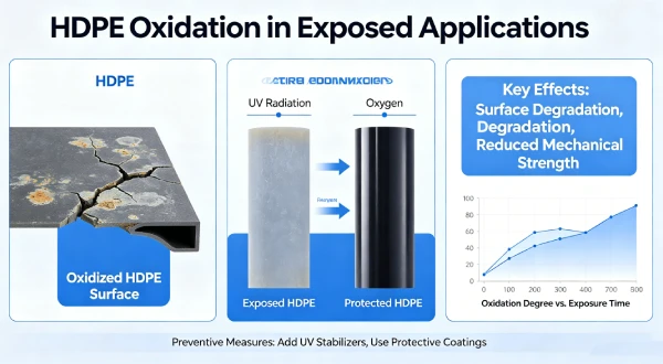
Exposed HDPE undergoes oxidation through two primary mechanisms: photo-oxidation from UV radiation (280–400 nm) and thermo-oxidation from elevated surface temperatures. Both generate free radicals that cause chain scission, reducing molecular weight and surface ductility. The oxidation rate is governed by UV intensity, temperature, oxygen availability, and carbon black protection effectiveness.
Q2: How deep does UV oxidation penetrate HDPE?
UV radiation penetrates only the surface layer of HDPE — approximately 0.1–0.3mm depending on carbon black content and dispersion. Carbon black absorbs UV radiation and converts it to harmless heat, but insufficient or poorly dispersed carbon black allows UV penetration to greater depth.
Q3: What surface temperature does HDPE reach in direct sunlight?
Exposed black HDPE surfaces can reach 60–80°C in direct sunlight depending on ambient temperature, wind speed, and solar intensity. This is significantly higher than ambient air temperature and dramatically accelerates thermo-oxidative degradation. Surface temperature measurements are essential for oxidation rate prediction.
Q4: How does carbon black protect HDPE from UV degradation?
Carbon black (2–3% by weight) absorbs UV radiation across the solar spectrum, preventing photo-oxidative chain scission. UV absorption efficiency depends on particle size, structure, and dispersion. Poor dispersion creates UV-transparent zones where oxidation initiates. ASTM D5596 requires dispersion rating ≥ 1 for proper protection.
Q5: Can oxidized HDPE be welded?
Oxidized surface layers cannot be reliably fusion-welded. The degraded surface lacks the reactive sites and molecular mobility required for proper molecular interdiffusion during welding. Surface scraping (removing 0.2–0.5mm) may restore weldability if oxidation is superficial. Severe oxidation requires liner replacement.
Q6: How long can HDPE be exposed before significant oxidation occurs?
Exposure duration depends on UV intensity, temperature, and carbon black protection. With proper carbon black (2.5–3.0%, dispersion rating ≥ 1), HDPE typically maintains integrity for 6–12 months of continuous exposure in temperate climates. Tropical exposure may degrade within 3–6 months. HP-OIT monitoring provides site-specific guidance.
Q7: What is the relationship between HP-OIT and surface oxidation?
HP-OIT testing of surface samples measures remaining antioxidant capacity in the UV-degraded layer. Surface HP-OIT declines faster than bulk HP-OIT due to UV depletion of antioxidants. Surface HP-OIT below 200 minutes indicates significant oxidation. Surface HP-OIT below 100 minutes indicates advanced degradation requiring intervention.
Q8: How does thermal cycling affect exposed HDPE?
Daily thermal cycling (night 10–20°C to day 60–80°C surface) creates cyclic expansion-contraction stress. Over time, this stress causes surface micro-cracking at oxidized zones, allowing deeper oxygen penetration and accelerating oxidation. Cracked surfaces also lose carbon black protection through erosion.
Q9: What are the visual signs of HDPE oxidation?
Visual indicators include: surface discolouration (fading from black to grey/brown), chalking (white powdery surface), surface cracking (fine crazing or alligator cracking), loss of gloss, and surface erosion. These signs typically appear after HP-OIT has already declined significantly.
Q10: Can oxidation be reversed or repaired?
Oxidation is irreversible — chain scission cannot be reversed. Shallow surface oxidation (0.1–0.2mm) may be removed by scraping for welding. Deeper oxidation requires liner replacement or capping with a new protection layer. Prevention through carbon black specification and UV protection is the only effective strategy.
3️⃣ Why HDPE Is Used — Material Science Focus
HDPE dominates exposed geomembrane applications due to its excellent chemical resistance, high tensile strength, and ability to incorporate UV-protective carbon black. However, all HDPE grades are susceptible to oxidative degradation when exposed to UV radiation and elevated temperatures. Understanding this vulnerability is essential for specification and protection design.
Chemical Resistance in Exposed Applications: HDPE resists the full range of process solutions encountered in heap leach pads (cyanide solutions, acid mine drainage), wastewater lagoons (municipal effluent, industrial wastewater), and mining tailings ponds (metallurgical solutions, acidic slurries). However, oxidising agents (e.g., hydrogen peroxide, chlorine, hypochlorite) can accelerate chemical oxidation of the exposed surface.
UV Protection Through Carbon Black: Carbon black (2–3% by weight, ASTM D4218) is the primary UV protectant for HDPE. The carbon black particles absorb UV radiation and convert it to harmless heat. Protection effectiveness depends on:
- Particle size: Finer particles (20–30nm) provide more surface area for UV absorption
- Structure: High-structure carbon black (branched aggregates) provides better UV attenuation
- Dispersion: Uniform dispersion (ASTM D5596 rating ≥ 1) prevents UV-transparent zones
Oxidative Induction Time (OIT vs HP-OIT): Standard OIT (ASTM D3895) tests antioxidant activity at 200°C under nitrogen. High-Pressure OIT (ASTM D5885) tests at 150°C under 3.5 MPa oxygen. HP-OIT is more relevant for exposed applications as it better represents the oxidative environment. GRI-GM13 requires OIT ≥ 100 minutes or HP-OIT ≥ 400 minutes for new material.
Surface vs Bulk Properties: In exposed applications, the surface layer (0.1–0.3mm depth) degrades faster than the bulk material due to UV penetration and oxygen availability. HP-OIT testing of surface samples provides early warning of oxidation, while bulk testing (from core samples) indicates the remaining base material condition.
Alternatives Comparison: HDPE vs Other Liner Materials for Exposed Applications
| Property | HDPE | LLDPE | fPP | PVC | EPDM |
|---|---|---|---|---|---|
| Key limitation for exposed use | Surface oxidation | Lower puncture/UV resistance | Lower tensile strength | Plasticizer loss and UV degradation | High cost, limited welding |
| UV resistance (with carbon black) | Excellent | Good | Good | Poor (requires protection) | Good (requires formulation) |
| Surface temperature tolerance | 60–80°C | 60–70°C | 50–60°C | 60–80°C | N/A |
| Field weldability after oxidation | Poor (requires scraping) | Poor (requires scraping) | Fair (hot air) | Poor (solvent weld fails) | Poor (adhesive weld fails) |
| UV protection mechanism | Carbon black | Carbon black | Carbon black | UV stabilisers | Carbon black + HALS |
| Cost relative to HDPE | 1.0x | 1.0–1.1x | 1.5–2.0x | 1.2–1.5x | 2.0–3.0x |
4️⃣ UV Radiation and Photo-Oxidation Mechanisms
Photo-oxidation is the primary degradation mechanism for exposed HDPE. UV radiation (280–400 nm) has sufficient energy (3.1–4.4 eV) to break C-H and C-C bonds in the polymer chain, generating free radicals that initiate oxidative degradation.
UV Spectrum and HDPE Absorption: HDPE absorbs UV radiation primarily in the 280–350 nm range. Carbon black absorption is effective across the full UV spectrum (280–400 nm), providing broad-spectrum protection. UV-visible spectroscopy of degraded HDPE shows increased absorption at 320–360 nm, corresponding to formation of carbonyl and unsaturated groups.
Photo-Oxidation Mechanism:
- Initiation: UV radiation breaks polymer bonds, generating free radicals (R•)
- Propagation: Radicals react with oxygen to form peroxy radicals (ROO•), which abstract hydrogen from adjacent chains
- Chain Scission: Peroxy radicals decompose to form carbonyl groups (C=O) and break the polymer backbone
- Termination: Radicals combine or are neutralised by antioxidants
Degradation Depth: UV radiation penetrates only the surface layer of HDPE. With carbon black protection, penetration depth is approximately 0.1–0.2mm. Without carbon black (or with poor dispersion), penetration can reach 0.3–0.5mm. This surface-limited degradation creates a brittle skin that cracks under thermal stress, allowing deeper oxygen penetration and propagation of thermo-oxidative degradation.
Photo-Oxidation Products: Degraded HDPE surface shows:
- Carbonyl groups (C=O) detectable by FTIR spectroscopy (peak at 1715 cm⁻¹)
- Unsaturated groups (C=C) detectable by FTIR (peak at 1640 cm⁻¹)
- Increased surface stiffness measured by nanoindentation
- Reduced elongation at break (ASTM D638) of surface micro-tensile samples
UV Intensity Factors: Solar UV intensity varies significantly with:
- Latitude: Tropical locations (0–23°) receive 2–3x higher UV intensity than temperate locations (40–50°)
- Altitude: UV intensity increases by 10–15% per 1000m elevation
- Season: Summer UV intensity is 2–4x higher than winter (Northern Hemisphere)
- Cloud cover: Overcast reduces UV intensity by 40–70%
- Reflectivity: Water surfaces reflect 10–30% of incident UV, doubling exposure
Photo-Oxidation Depth Profile
text
┌─────────────────────────────────────────────────────────────────────────────┐
│                    PHOTO-OXIDATION DEPTH PROFILE                           │
│                                                                             │
│  Surface                                                                     │
│    ↓                                                                        │
│  0.0mm ══════════════════════════════════════════════════════════════════   │
│         ║  SEVERELY OXIDISED ZONE                                           │
│         ║  • HP-OIT < 100 minutes                                           │
│         ║  • Carbonyl index > 0.5 (FTIR)                                   │
│         ║  • Surface crazing, loss of gloss                                 │
│         ║  • Elongation reduction > 50%                                     │
│  0.1mm ══════════════════════════════════════════════════════════════════   │
│         ║  MODERATELY OXIDISED ZONE                                         │
│         ║  • HP-OIT 100-200 minutes                                         │
│         ║  • Carbonyl index 0.2-0.5                                         │
│         ║  • Reduced surface ductility                                      │
│  0.2mm ══════════════════════════════════════════════════════════════════   │
│         ║  TRANSITION ZONE                                                  │
│         ║  • HP-OIT 200-300 minutes                                         │
│         ║  • Limited oxidation (UV penetration limit)                       │
│         ║  • Properties approaching bulk                                    │
│  0.3mm ══════════════════════════════════════════════════════════════════   │
│         ║  UNOXIDISED BULK MATERIAL                                         │
│         ║  • HP-OIT ≥ 400 minutes                                           │
│         ║  • Full mechanical properties retained                            │
│         ║  • Carbon black protection intact                                 │
│  0.5mm ══════════════════════════════════════════════════════════════════   │
│                                                                             │
│  ⚠️ UV penetration depth depends on carbon black content and dispersion     │
│  📌 Carbon black (2.5-3.0%, dispersion rating ≥ 1) limits oxidation to     │
│      ≤ 0.2mm surface layer                                                  │
└─────────────────────────────────────────────────────────────────────────────┘
5️⃣ Thermo-Oxidative Degradation in Exposed Conditions
Thermo-oxidative degradation occurs when elevated surface temperatures accelerate the oxidation rate of HDPE. In exposed applications, surface temperatures in direct sunlight can reach 60–80°C, dramatically increasing degradation kinetics.
Arrhenius Kinetics for Thermo-Oxidation: HDPE oxidation follows Arrhenius kinetics: k = A × exp(-Ea/RT), where Ea is activation energy (80–100 kJ/mol for HDPE). The practical implication: reaction rate doubles per 10°C temperature increase. At 60°C surface temperature, degradation proceeds approximately 16 times faster than at 20°C. At 80°C, it proceeds approximately 64 times faster.
Surface Temperature Measurement: Surface temperature of exposed black HDPE depends on:
- Ambient temperature: Each 1°C ambient increase raises surface temperature by 0.8–1.0°C
- Solar radiation: Each 100 W/m² increase raises surface temperature by 3–5°C
- Wind speed: Higher wind reduces surface temperature by 5–15°C
- Emissivity: Black HDPE has emissivity of 0.85–0.95, absorbing 85–95% of incident solar radiation
Thermal-Oxidative Mechanism:
- Thermal Initiation: Heat energy (Ea ≈ 80–100 kJ/mol) breaks polymer bonds, generating free radicals
- Oxygen Diffusion: Oxygen penetrates the surface layer (0.2–0.5mm depth at 60–80°C)
- Autocatalysis: Peroxy radicals abstract hydrogen from adjacent chains, creating chain reactions
- Chain Scission: Peroxy radicals decompose, breaking polymer backbone and reducing molecular weight
Surface Temperature vs Oxidation Rate
text
┌─────────────────────────────────────────────────────────────────────────────┐
│                    SURFACE TEMPERATURE vs OXIDATION RATE                   │
│                                                                             │
│  Oxidation Rate (Relative to 20°C = 1x)                                    │
│  │                                                                          │
│  64x ┤                                    ●  (80°C, 64x)                   │
│      │                                   │                                  │
│  60x ┤                                   │                                  │
│      │                                   │                                  │
│  56x ┤                                   │                                  │
│      │                                   │                                  │
│  52x ┤                                   │                                  │
│      │                                   │                                  │
│  48x ┤                                   │                                  │
│      │                                   │                                  │
│  44x ┤                                   │                                  │
│      │                                   │                                  │
│  40x ┤                                   │                                  │
│      │                                   │                                  │
│  36x ┤                                   │                                  │
│      │                                   │                                  │
│  32x ┤                        ●  (70°C, 32x)                               │
│      │                       │                                              │
│  28x ┤                       │                                              │
│      │                       │                                              │
│  24x ┤                       │                                              │
│      │                       │                                              │
│  20x ┤                       │                                              │
│      │                       │                                              │
│  16x ┤            ●  (60°C, 16x)                                           │
│      │           │                                                          │
│  12x ┤           │                                                          │
│      │           │                                                          │
│   8x ┤     ●  (50°C, 8x)                                                   │
│      │    │                                                                 │
│   4x ┤  ●  (40°C, 4x)                                                      │
│      │ │                                                                   │
│   2x ┤ ●  (30°C, 2x)                                                       │
│      ││                                                                     │
│   1x ┤●  (20°C, 1x)                                                        │
│      │                                                                      │
│   0x └─────────────────────────────────────────────────────────────────     │
│      20°C  30°C  40°C  50°C  60°C  70°C  80°C                             │
│                            Surface Temperature                              │
│                                                                             │
│  ⚠️ Oxidation rate doubles per 10°C temperature increase                    │
│  📌 At 80°C, oxidation occurs 64x faster than at 20°C                      │
└─────────────────────────────────────────────────────────────────────────────┘
Surface Temperature vs Oxidation Rate Table:
| Surface Temperature | Relative Oxidation Rate (20°C = 1x) | Time to 50% HP-OIT Depletion |
|---|---|---|
| 20°C | 1x | 20–30 years |
| 30°C | 2x | 10–15 years |
| 40°C | 4x | 5–8 years |
| 50°C | 8x | 2.5–4 years |
| 60°C | 16x | 1.2–2 years |
| 70°C | 32x | 0.6–1 year |
| 80°C | 64x | 3–6 months |
Table scrolls horizontally on mobile
Combined UV + Thermo-Oxidation: In exposed applications, UV and thermo-oxidation act synergistically. UV photo-oxidation creates carbonyl groups and surface cracks that allow deeper oxygen penetration, increasing thermo-oxidation rate. Thermo-oxidation weakens the polymer, making it more susceptible to UV-induced chain scission. The combined effect is greater than the sum of individual mechanisms.
6️⃣ Carbon Black Protection — Specification and Performance
Carbon black is the most effective UV protectant for HDPE. Understanding the specification requirements and performance characteristics is essential for material selection.
Carbon Black Content (ASTM D4218): GRI-GM13 requires carbon black content of 2.0–3.0% by weight. Recommend 2.5–3.0% for exposed applications to maximise UV protection. Higher carbon black content (up to 3.5%) provides slightly improved UV protection but may reduce stress crack resistance and weldability.
Carbon Black Dispersion (ASTM D5596): Dispersion rating must be ≥ 1 (GRI-GM13 requirement). Rating 1 indicates good dispersion with no agglomerates > 50μm. Rating 2 indicates fair dispersion with agglomerates 50–100μm. Rating 3 indicates poor dispersion with agglomerates > 100μm. Poor dispersion creates UV-transparent zones where photo-oxidation initiates.
Carbon Black Particle Size: Optimal particle size for UV protection is 20–30nm (furnace black). Smaller particles provide higher surface area for UV absorption. Larger particles (50–100nm) are less effective. Resin supplier datasheets should specify carbon black type and particle size distribution.
Carbon Black Structure: High-structure carbon black (branched aggregates) provides better UV attenuation than low-structure (spherical) carbon black. ASTM D2414 measures carbon black structure by oil absorption number (OAN). Higher OAN indicates higher structure.
Carbon Black Content vs UV Protection
text
┌─────────────────────────────────────────────────────────────────────────────┐
│                    CARBON BLACK CONTENT vs UV PROTECTION                   │
│                                                                             │
│  UV Transmission (%)                                                        │
│  │                                                                          │
│  90 ┤  ● (0%, 90% transmission) — Unprotected                              │
│      │                                                                      │
│  80 ┤  │                                                                   │
│      │                                                                      │
│  70 ┤  │                                                                   │
│      │                                                                      │
│  60 ┤  │                                                                   │
│      │                                                                      │
│  50 ┤  │                                                                   │
│      │                                                                      │
│  40 ┤  │  ● (0.5%, 35% transmission) — Poor protection                     │
│      │  │                                                                  │
│  30 ┤  │  │                                                                │
│      │  │  │                                                               │
│  20 ┤  │  │  ● (1.0%, 12% transmission) — Marginal protection              │
│      │  │  │  │                                                            │
│  15 ┤  │  │  │  ● (1.5%, 4% transmission) — Moderate protection            │
│      │  │  │  │  │                                                         │
│  10 ┤  │  │  │  │  ● (2.0%, 1.5% transmission) — Good (GRI minimum)       │
│      │  │  │  │  │  │                                                      │
│   5 ┤  │  │  │  │  │  ● (2.5%, 0.3% transmission) — Excellent              │
│      │  │  │  │  │  │  │                                                   │
│   1 ┤  │  │  │  │  │  │  ● (3.0%, 0.1% transmission) — Excellent           │
│      │  │  │  │  │  │  │  │                                                │
│ 0.1 ┤  │  │  │  │  │  │  │  ● (3.5%, 0.05% transmission)                  │
│      │  │  │  │  │  │  │  │  │                                             │
│   0 └──┴──┴──┴──┴──┴──┴──┴──┴─────────────────                             │
│      0  0.5 1.0 1.5 2.0 2.5 3.0 3.5                                        │
│                         Carbon Black Content (%)                            │
│                                                                             │
│  Protection Level:  │ None │ Poor │ Marginal │ Moderate │ Good │ Excellent │
│  Recommended for    │  ❌   │  ❌  │    ❌    │    ❌   │  ⚠️  │    ✅     │
│  Exposed Application│       │      │         │         │      │           │
│                                                                             │
│  📌 Recommend 2.5-3.0% carbon black for exposed applications               │
└─────────────────────────────────────────────────────────────────────────────┘
UV Attenuation vs Carbon Black Content Table:
| Carbon Black Content (%) | UV Transmission (%) | Protection Effectiveness | Recommended for Exposed |
|---|---|---|---|
| 0% (unprotected) | 80–90% | None | ❌ No |
| 0.5% | 30–40% | Poor | ❌ No |
| 1.0% | 10–15% | Marginal | ❌ No |
| 1.5% | 3–5% | Moderate | ❌ No |
| 2.0% | 1–2% | Good (GRI-GM13 minimum) | ⚠️ Marginal |
| 2.5–3.0% | 0.1–0.5% | Excellent | ✅ Yes |
| 3.5% | < 0.1% | Excellent (may affect weldability) | ⚠️ Limited |
Table scrolls horizontally on mobile
Carbon Black Leaching and Erosion: In exposed applications, carbon black can be leached from the surface by:
- Rainwater: Slight leaching of surface carbon black over 5–10 years
- Wind abrasion: Removal of surface carbon black by wind-borne particles
- Chemical exposure: Some process solutions (e.g., cyanide) can leach carbon black
- Cleaning: Abrasive cleaning methods remove surface carbon black
Alternative UV Stabilisers: Some applications use UV stabilisers (HALS — Hindered Amine Light Stabilisers) in addition to carbon black. HALS stabilisers are free-radical scavengers that complement carbon black UV absorption. However, HALS are consumed over time and do not provide the permanent protection of carbon black.
Carbon Black Dispersion Quality
text
┌─────────────────────────────────────────────────────────────────────────────┐
│                    CARBON BLACK DISPERSION QUALITY                         │
│                                                                             │
│  EXCELLENT DISPERSION (Rating 1) — GRI-GM13 Requirement                     │
│  ┌─────────────────────────────────────────────────────────────────────┐   │
│  │  • Uniform dispersion of carbon black particles                       │   │
│  │  • No agglomerates > 50μm                                             │   │
│  │  • UV protection throughout surface layer                            │   │
│  │  • Oxidation limited to 0.1-0.2mm depth                             │   │
│  │  • Recommended for all exposed applications                          │   │
│  └─────────────────────────────────────────────────────────────────────┘   │
│                                                                             │
│  FAIR DISPERSION (Rating 2) — Acceptable for covered applications only      │
│  ┌─────────────────────────────────────────────────────────────────────┐   │
│  │  • Some agglomerates 50-100μm                                         │   │
│  │  • Localised UV-transparent zones                                     │   │
│  │  • Oxidation initiates at agglomerate edges                           │   │
│  │  • Surface degradation depth: 0.2-0.3mm                              │   │
│  │  • NOT RECOMMENDED for exposed applications                           │   │
│  └─────────────────────────────────────────────────────────────────────┘   │
│                                                                             │
│  POOR DISPERSION (Rating 3) — Not acceptable for any application           │
│  ┌─────────────────────────────────────────────────────────────────────┐   │
│  │  • Large agglomerates > 100μm                                         │   │
│  │  • Extensive UV-transparent zones                                    │   │
│  │  • Rapid oxidation at agglomerate boundaries                         │   │
│  │  • Surface degradation depth: 0.3-0.5mm                             │   │
│  │  • REJECT material                                                    │   │
│  └─────────────────────────────────────────────────────────────────────┘   │
│                                                                             │
│  ⚠️ Poor dispersion creates UV pathways through the liner                   │
│  📌 Specify carbon black dispersion rating ≥ 1 (ASTM D5596)                │
└─────────────────────────────────────────────────────────────────────────────┘
7️⃣ Combined Degradation Mechanisms — UV + Heat + Stress
In exposed applications, UV radiation, elevated temperature, and mechanical stress act synergistically to accelerate oxidation beyond the sum of individual effects.
UV + Thermo-Oxidative Synergy: UV photo-oxidation creates carbonyl groups and surface cracks. These cracks allow oxygen to penetrate deeper into the polymer. The additional oxygen accelerates thermo-oxidation, which in turn creates more carbonyl groups and crack sites. This positive feedback loop accelerates degradation exponentially.
UV + Mechanical Stress: UV-degraded surfaces develop micro-cracks under thermal cycling stress. These cracks propagate deeper into the material, exposing fresh polymer to UV radiation and oxygen. Once cracks reach 0.3–0.5mm depth (below the carbon-black-protected layer), degradation accelerates dramatically.
Thermal Stress + UV Degradation: Daily thermal cycling (night 10–20°C to day 60–80°C surface) creates cyclic stress of 1–5 MPa. This stress, combined with UV-induced surface embrittlement, causes surface cracking that would not occur with either stress or UV alone.
Oxygen Availability in Exposed Applications: Exposed liners have unlimited oxygen availability from the atmosphere, unlike covered liners where oxygen is limited. This continuous oxygen supply sustains oxidation reactions and prevents oxygen-depletion limitations found in buried applications.
Degradation Acceleration Factors — Combined Mechanisms
text
┌─────────────────────────────────────────────────────────────────────────────┐
│                    COMBINED DEGRADATION MECHANISMS                         │
│                                                                             │
│  UV Photo-Oxidation                                                         │
│  ┌────────────────────────────────────────────────────────────────────┐    │
│  │  • Surface carbonyl formation                                       │    │
│  │  • Micro-crack initiation                                           │    │
│  │  • Surface embrittlement                                            │    │
│  └────────────────────────────────────────────────────────────────────┘    │
│                                    │                                        │
│                                    ↓                                        │
│                        ┌───────────────────────┐                          │
│                        │  SYNERGISTIC EFFECTS  │                          │
│                        ├───────────────────────┤                          │
│                        │ • Deeper O₂ penetration│                        │
│                        │ • Accelerated oxidation│                        │
│                        │ • Crack propagation    │                        │
│                        └───────────────────────┘                          │
│                          ↑                 ↑                               │
│  ┌───────────────────────┘                 └───────────────────────┐      │
│  │                                                                  │      │
│  ↓                                                                  ↓      │
│  Thermo-Oxidation                                               Mechanical  │
│  ┌────────────────────────────────────────────────────────────┐    Stress   │
│  │ • Elevated surface temperature (60-80°C)                    │    ┌──────┐│
│  │ • Oxidation rate 16-64x faster than 20°C                   │    │Wrinkles││
│  │ • Thermal chain scission                                    │    │Contrac-││
│  │ • Antioxidant depletion                                     │    │ tion  ││
│  └────────────────────────────────────────────────────────────┘    │Stress ││
│                                                                     └──────┘│
│                                                                             │
│  Combined Degradation Acceleration:                                        │
│  ┌─────────────────────────────────────────────────────────────────────┐   │
│  │  Condition                  │ Relative Degradation Rate             │   │
│  ├─────────────────────────────────────────────────────────────────────┤   │
│  │  Covered, 20°C, no stress   │ 1x (baseline)                        │   │
│  │  Covered, 20°C, stress      │ 1.5-2x                               │   │
│  │  Exposed, UV only (carbon black) │ 2-3x                            │   │
│  │  Exposed, UV + 40°C surface │ 8-12x                                │   │
│  │  Exposed, UV + 60°C surface │ 24-36x                               │   │
│  │  Exposed, UV + 60°C + stress│ 36-60x                               │   │
│  └─────────────────────────────────────────────────────────────────────┘   │
│                                                                             │
│  ⚠️ Combined effects are GREATER THAN SUM of individual effects           │
│  📌 Stress management and temperature control are critical prevention      │
└─────────────────────────────────────────────────────────────────────────────┘
Critical Exposure Duration: The combined effect of UV + temperature + stress means that exposed HDPE typically has a service life of 3–10 years before significant oxidation occurs, compared to 30–100+ years for covered applications. This shorter service life must be accounted for in design, specification, and maintenance planning.
8️⃣ Real Engineering Failure Cases
Case 1: Photo-Oxidation Surface Embrittlement — Chilean Heap Leach Pad, 2019
Specification used: 1.5mm HDPE, carbon black 2.0% (GRI-GM13 minimum), dispersion rating 2. Exposed for 18 months before solution placement.
Observed failure: Surface embrittlement to 0.3mm depth. HP-OIT surface samples measured 80 minutes (initial 420 minutes). Surface cracking visible under magnification. Leak detection survey showed increased leakage through surface cracks after solution loading.
Timeline:
text
2019: 1.5mm HDPE installed, carbon black 2.0%, dispersion rating 2
    ↓ Exposed 18 months in high-UV Chilean desert (altitude 2000m)
2021: Surface embrittlement detected, HP-OIT 80min
    ↓ Surface cracking at 0.3mm depth
2021: Solution loading commenced, leaks detected at cracks
    ↓
    ↓ Repair cost: $1.2M (surface patches + additional liner)
    ↓
    ↓ Lesson: For high-UV/high-altitude sites, specify 2.5-3.0% carbon black
Root cause: Carbon black content (2.0%) was marginal for high-UV tropical desert application. Dispersion rating 2 created UV-transparent zones where oxidation initiated. Extended 18-month exposure before solution placement allowed oxidation to progress below the carbon-black-protected layer.
Engineering lesson: For high-UV locations (tropical, high-altitude, desert), specify carbon black content 2.5–3.0% and dispersion rating ≥ 1. Limit exposure duration to 6 months maximum. HP-OIT monitor surface samples at 3-month intervals during exposure.
Case 2: Thermal Oxidation + Stress Cracking — Australian Wastewater Lagoon, 2020
Specification used: 2.0mm HDPE, carbon black 2.5%, dispersion rating 1. Lagoon operating at 35°C wastewater temperature, exposed surface temperature 65°C in direct sunlight.
Observed failure: Surface cracking after 3 years. Cracks propagated through 2.0mm liner at wrinkle locations. Leakage rate increased from 5 L/day to 450 L/day within 6 months.
Timeline:
text
2020: 2.0mm HDPE installed, wastewater lagoon, 35°C wastewater
    ↓ Surface temp 65°C, diurnal thermal cycling
2023: Surface cracking at wrinkles, cracking propagated through liner
    ↓ Leakage increased 5 L/day → 450 L/day
2023: Liner replacement initiated
    ↓
    ↓ Cost: $3.8M (replacement + lagoon downtime + environmental)
    ↓
    ↓ Lesson: Exposed applications require stress management (wrinkle prevention)
Root cause: Thermal cycling stress at wrinkle locations, combined with elevated surface temperature (65°C), accelerated oxidation at stress concentration points. Arrhenius modelling predicted 16x oxidation rate at 65°C compared to 20°C. Surface cracking progressed to through-liner failure within 3 years.
Engineering lesson: For exposed high-temperature applications, eliminate wrinkles through careful installation. Seam orientation parallel to contours. Consider light-coloured liners to reduce surface temperature. HP-OIT monitor annually.
Case 3: UV + Chemical Oxidation — Brazilian Mining Tailings Pond, 2021
Specification used: 2.0mm HDPE, carbon black 2.5%, dispersion rating 1. Tailings solution containing cyanide and oxidising agents.
Observed failure: Surface oxidation accelerated by chemical attack. HP-OIT after 2 years measured 90 minutes (initial 430 minutes). Extensive surface erosion and pitting. Leakage through pitted areas.
Timeline:
text
2021: 2.0mm HDPE installed, tailings solution with cyanide/oxidising agents
    ↓ UV + chemical oxidation combined attack
2023: HP-OIT 90min, surface pitting and erosion
    ↓ Leakage through pitted areas
2023: Liner replacement with chemically-resistant grade
    ↓
    ↓ Cost: $2.5M (replacement + environmental monitoring)
    ↓
    ↓ Lesson: Chemical oxidation + UV exposure requires higher carbon black
Root cause: Chemical oxidation from cyanide and oxidising agents combined with UV photo-oxidation. The two oxidation mechanisms consumed antioxidants faster than either alone. Carbon black 2.5% insufficient to protect against combined UV + chemical attack.
Engineering lesson: For aggressive chemical environments with UV exposure, specify HP-OIT ≥ 500 minutes and carbon black 3.0%. Consider surface protection (floating covers, shade structures). Annual HP-OIT monitoring with 6-month frequency if HP-OIT drops below 200 minutes.
Failure Case Cost Comparison
text
┌─────────────────────────────────────────────────────────────────────────────┐
│                    FAILURE CASE COST COMPARISON                            │
│                                                                             │
│  Cost ($M)                                                                  │
│  │                                                                          │
│  4.0 ┤                                                                      │
│      │                                                                      │
│  3.5 ┤    ●  (Australia, $3.8M)                                            │
│      │   │                                                                  │
│  3.0 ┤   │    ●  (Brazil, $2.5M)                                          │
│      │   │   │                                                              │
│  2.5 ┤   │   │                                                              │
│      │   │   │                                                              │
│  2.0 ┤   │   │                                                              │
│      │   │   │                                                              │
│  1.5 ┤   │   │    ●  (Chile, $1.2M)                                        │
│      │   │   │   │                                                          │
│  1.0 ┤   │   │   │                                                          │
│      │   │   │   │                                                          │
│  0.5 ┤   │   │   │                                                          │
│      │   │   │   │                                                          │
│    0 └───┴───┴───┴──────────────────────────────────────                   │
│           Chile    Brazil    Australia                                      │
│           (UV)     (UV+Chem) (UV+Heat+Stress)                              │
│                                                                             │
│  ⚠️ Average failure cost: $2.5M                                            │
│  📌 Prevention investment: $50-100k = 2-4% of potential failure cost      │
└─────────────────────────────────────────────────────────────────────────────┘
9️⃣ Comparison With Alternative Liner Systems for Exposed Applications
| Property | HDPE (2.0mm) | LLDPE (1.5mm) | PVC (1.5mm) | EPDM (1.5mm) | GCL |
|---|---|---|---|---|---|
| UV resistance (carbon black) | Excellent (2.5–3.0%) | Good (carbon black) | Poor (requires coating) | Good (carbon black + HALS) | N/A (not exposed) |
| Surface temperature tolerance | 60–80°C | 60–70°C | 50–60°C | 60–80°C | N/A |
| Surface oxidation depth (5 years exposure) | 0.1–0.3mm | 0.2–0.4mm | 0.5–1.0mm (plasticizer loss) | 0.1–0.2mm | N/A |
| Field weldability after exposure | Poor (scraping required) | Poor (scraping required) | Poor (solvent weld fails) | Poor (adhesive weld fails) | N/A |
| UV protection mechanism | Carbon black | Carbon black | UV stabilisers | Carbon black + HALS | N/A |
| Chemical oxidation resistance | Good | Good | Poor (plasticizer loss) | Fair | N/A |
| Exposed application suitability | ✅ Recommended (with carbon black) | ⚠️ Limited (shorter service life) | ❌ Not recommended | ⚠️ Limited (cost) | ❌ Not exposed |
| Cost relative to HDPE | 1.0x | 1.0–1.1x | 1.2–1.5x | 2.0–3.0x | 0.6–0.8x |
Table scrolls horizontally on mobile
🔟 Prevention Strategies and Monitoring
Carbon Black Specification:
- ✅ Content: 2.5–3.0% (ASTM D4218) — higher than GRI-GM13 minimum
- ✅ Dispersion: Rating ≥ 1 (ASTM D5596) — critical for uniform protection
- ✅ Particle size: 20–30nm (furnace black)
- ✅ Structure: High-structure (OAN ≥ 100 cc/100g)
UV Exposure Management:
- ✅ Limit exposure duration: ≤ 6 months for temperate, ≤ 3 months for tropical
- ✅ Covering: Install temporary UV-protective covers during construction delays
- ✅ Storage: Store rolls under cover, limit UV exposure during storage
- ✅ Light-coloured liners: Consider light-coloured HDPE for temperature reduction
Stress Management:
- ✅ Wrinkle prevention: 2–3% slack during installation, thermal accommodation
- ✅ Seam orientation: Parallel to slope contours
- ✅ Anchor systems: Tension relief at edges
- ✅ Subgrade: Particle size ≤ 6mm, compaction ≥ 95% Standard Proctor
Monitoring Program:
- ✅ Surface HP-OIT testing: Baseline from material certification, then every 6–12 months
- ✅ Visual inspection: Monthly for surface crazing, chalking, discolouration
- ✅ Surface temperature monitoring: Continuous or daily measurements
- ✅ Leak location survey: Annual or biennial depending on risk
- ✅ FTIR analysis: Surface carbonyl index for oxidation tracking
- ✅ Documentation retention: All results for lifetime of facility
Surface HP-OIT Action Thresholds
| Surface HP-OIT Value | Risk Level | Action Required | Monitoring Frequency |
|---|---|---|---|
| ≥ 400 minutes | Normal | Continue routine monitoring | Annual testing |
| 300–400 minutes | Low | Increase awareness, verify carbon black protection | Annual testing |
| 200–300 minutes | Moderate | Increased monitoring, evaluate surface degradation | 6-month testing |
| 100–200 minutes | High | Advanced depletion — plan for intervention | Quarterly testing |
| < 100 minutes | Critical | Immediate intervention required | Monthly testing + repair plan |
Table scrolls horizontally on mobile
1️⃣1️⃣ Professional Engineering Recommendation
Oxidation Risk Management Matrix for Exposed Applications:
| Oxidation Risk Level | Carbon Black Content | Dispersion Rating | Surface HP-OIT | Monitoring Frequency | Max Exposure Duration |
|---|---|---|---|---|---|
| Low: Temperate climate, < 30°C surface, limited UV | ≥ 2.5% | ≥ 1 | ≥ 400 min | Annual | 12 months |
| Moderate: Temperate, 30–50°C surface, moderate UV | ≥ 2.5% | ≥ 1 | ≥ 300 min | 6-month | 6 months |
| High: Tropical, 50–70°C surface, high UV, chemical exposure | ≥ 3.0% | ≥ 1 | ≥ 400 min (initial) | Quarterly | 3 months |
| Extreme: Desert/tropical, > 70°C surface, aggressive chemicals | ≥ 3.0% + HALS | ≥ 1 | ≥ 500 min (initial) | Monthly | 1 month |
Table scrolls horizontally on mobile
When to Specify Enhanced UV Protection:
- Tropical latitudes (0–23°) with high UV intensity
- High-altitude sites (> 1500m) with increased UV
- Desert environments with surface temperatures > 60°C
- Aggressive chemical exposure (oxidising agents, acids)
- Extended construction periods (> 6 months exposure)
- Critical containment applications (hazardous waste, potable water)
Quality Assurance Requirements:
- ✅ Material certification: GRI-GM13 compliance + carbon black dispersion rating ≥ 1
- ✅ Resin supplier datasheet: Confirm carbon black particle size and structure
- ✅ HP-OIT verification: Baseline testing of material upon delivery
- ✅ Installation monitoring: Surface HP-OIT at 3-month intervals during exposure
- ✅ Visual inspection: Weekly during construction exposure
- ✅ Documentation retention: All test results for lifetime of facility
1️⃣2️⃣ FAQ Section
Q1: What causes HDPE oxidation in exposed applications?
HDPE oxidation in exposed applications is caused by UV radiation (photo-oxidation) and elevated surface temperatures (thermo-oxidation). Both mechanisms generate free radicals that cause chain scission, reducing molecular weight and surface ductility. Carbon black provides UV protection but does not prevent thermo-oxidation.
Q2: How does carbon black protect HDPE from UV degradation?
Carbon black (2–3% by weight) absorbs UV radiation across the solar spectrum, converting it to harmless heat. Protection effectiveness depends on carbon black content, particle size (20–30nm), structure (high-structure preferred), and dispersion (ASTM D5596 rating ≥ 1).
Q3: What surface temperature does HDPE reach in direct sunlight?
Exposed black HDPE surfaces can reach 60–80°C in direct sunlight depending on ambient temperature, solar intensity, and wind speed. This is significantly higher than ambient air temperature and accelerates thermo-oxidative degradation by 4–64x compared to 20°C.
Q4: How deep does UV oxidation penetrate HDPE?
UV radiation penetrates only the surface layer of HDPE — approximately 0.1–0.3mm depending on carbon black content and dispersion. With carbon black 2.5–3.0% and dispersion rating ≥ 1, oxidation depth is limited to 0.1–0.2mm.
Q5: How long can HDPE be exposed before significant oxidation occurs?
With proper carbon black protection (2.5–3.0%, dispersion rating ≥ 1), HDPE maintains integrity for 6–12 months of continuous exposure in temperate climates. Tropical exposure may degrade within 3–6 months. HP-OIT monitoring provides site-specific guidance.
Q6: Can oxidized HDPE be welded?
Oxidized surface layers cannot be reliably fusion-welded. The degraded surface lacks the reactive sites and molecular mobility required for proper molecular interdiffusion. Surface scraping (0.2–0.5mm removal) may restore weldability if oxidation is superficial. Severe oxidation requires liner replacement.
Q7: What are the visual signs of HDPE oxidation?
Visual indicators include: surface discolouration (fading from black to grey/brown), chalking (white powdery surface), surface cracking (fine crazing or alligator cracking), loss of gloss, and surface erosion. These signs typically appear after HP-OIT has already declined significantly.
Q8: How do I monitor HDPE oxidation in the field?
Surface HP-OIT testing (ASTM D5885) is the primary monitoring tool. Sample the surface layer (0.1–0.3mm depth) and test at 3–12 month intervals depending on risk. Visual inspection for surface crazing, discolouration, and chalking. FTIR analysis for carbonyl index.
Q9: What is the difference between surface HP-OIT and bulk HP-OIT?
Surface HP-OIT tests the top 0.1–0.3mm layer (UV-exposed zone). Bulk HP-OIT tests the material core. Surface HP-OIT decreases faster due to UV depletion. Surface HP-OIT below 200 minutes requires investigation. Bulk HP-OIT indicates remaining material condition.
Q10: Can oxidation be prevented in exposed applications?
Oxidation cannot be prevented entirely but can be managed through: carbon black specification (2.5–3.0%, dispersion rating ≥ 1), limiting exposure duration, temperature management (light-coloured liners, shade structures), stress management (wrinkle prevention), and regular HP-OIT monitoring.
1️⃣3️⃣ Technical Conclusion
HDPE geomembrane oxidation in exposed applications is driven by the synergistic effects of UV radiation, elevated surface temperatures, atmospheric oxygen, and mechanical stress. Carbon black provides the primary UV protection, but effectiveness depends on content (2.5–3.0% recommended), particle size, structure, and dispersion (ASTM D5596 rating ≥ 1). Surface temperatures in direct sunlight can reach 60–80°C, accelerating thermo-oxidative degradation by 16–64 times compared to 20°C conditions.
The oxidation mechanism follows a surface-limited degradation profile with UV penetration depth of 0.1–0.3mm. Photo-oxidation creates carbonyl groups and surface micro-cracks, allowing deeper oxygen penetration and accelerating thermo-oxidation. Thermal cycling and mechanical stress create additional crack propagation pathways. The combined effects of UV, heat, and stress reduce exposed HDPE service life to 3–10 years, compared to 30–100+ years for covered applications.
HP-OIT monitoring of surface samples provides the earliest warning of oxidation, with values below 200 minutes requiring investigation and below 100 minutes indicating advanced degradation. Visual inspection for surface crazing, chalking, and discolouration complements HP-OIT monitoring. Field welding of oxidized surfaces is unreliable without surface scraping.
Prevention strategies focus on carbon black specification (2.5–3.0%, dispersion rating ≥ 1), limiting exposure duration (3–6 months maximum for tropical sites), temperature management through light-coloured liners or shade structures, stress management through wrinkle prevention, and regular monitoring. The cost of prevention through proper specification and monitoring ($10,000–50,000 per installation) is far lower than failure remediation ($500,000–5,000,000).
Lifecycle thinking must guide oxidation management for exposed applications. The decision on carbon black content, UV protection strategy, monitoring frequency, and exposure duration is ultimately one of risk tolerance, site conditions, regulatory compliance, and professional engineering judgement applied to the specific application.
📚 Related Technical Guides
HDPE Geomembrane HP-OIT Testing: A Field Monitoring Engineer's ManualCarbon Black Dispersion and UV Protection: Specification and Quality Control for Exposed LinersSurface Temperature Effects on Geomembrane Longevity: Measurement and ModellingGeomembrane UV Exposure Management: Construction Planning and Protection StrategiesHDPE Geomembrane Failure Investigation: Oxidation Root Cause Analysis