HDPE Seam Fishmouth Defects Guide 2026 | Prevention & Quality Control
Application Guide 2026-07-06
Author: Senior Geomembrane Engineer, P.E. — 15+ years field experience in geomembrane welding quality management, seam defect analysis, failure investigation, and CQA across landfill, mining, and wastewater applications
Reviewer: Geosynthetics Materials Specialist
Last Updated: July 2, 2026
Read Time: 12 minutes
📅 Review Cycle: This guide is updated quarterly. Last verified: July 2, 2026
📋 Executive Summary — For Engineers in a Hurry
- Fishmouth defects are the most common seam defect in HDPE geomembrane installations, occurring at weld terminations, T-junctions, and intersections where panel geometry creates stress concentrations
- Fishmouths create stress concentration factors of 3–10x at the notch tip, initiating environmental stress cracking (ESC) within 2–5 years of installation
- Weld integrity is reduced by 30–50% at fishmouth locations due to incomplete fusion and stress concentration
- Prevention requires proper panel layout, 3–5m offset at T-junctions, corner radii ≥ 1m, and careful welding sequence
- Acceptance criteria: Fishmouth notches > 5mm depth require repair; notches > 10mm require section replacement
- CQA requirements: 100% visual inspection of all weld intersections, with destructive testing targeting fishmouth locations
⚠️ Critical Engineering Statement — Fishmouth Prevention > Weld Strength for Long-Term Performance
Fishmouth defects are the most common cause of seam failure in HDPE liner installations, often initiating ESC and leakage within 2–5 years of installation.
- Stress concentration at fishmouth notches (3–10x) creates local stresses exceeding ESC threshold (2–5 MPa)
- Weld integrity reduces by 30–50% at fishmouth locations due to incomplete fusion
- ESC initiates at fishmouth notches in 2–5 years, versus 10–20 years for defect-free seams
- Leak detection at fishmouths accounts for 20–30% of all detected leaks
A properly designed panel layout with no fishmouths will outperform a poorly designed layout with multiple fishmouths. Installation quality — specifically fishmouth prevention — outweighs weld strength specification for long-term performance.
📑 Table of Contents
1️⃣ Search Intent Introduction
2️⃣ Common Engineering Questions About Fishmouth Defects
3️⃣ Why HDPE Is Used — Material Science Focus
4️⃣ Fishmouth Formation Mechanisms
5️⃣ Stress Concentration and Damage Mechanisms
6️⃣ Weld Integrity Reduction at Fishmouths
7️⃣ Fishmouth Effects on Long-Term Performance
8️⃣ Real Engineering Failure Cases
9️⃣ Comparison With Alternative Liner Systems
🔟 Fishmouth Prevention and CQA Requirements
1️⃣1️⃣ Professional Engineering Recommendation
1️⃣2️⃣ FAQ Section
1️⃣3️⃣ Technical Conclusion
1️⃣ Search Intent Introduction
This guide addresses the engineering question of how fishmouth defects form in HDPE geomembrane seams, why they compromise long-term performance, and how to prevent them during installation. The primary audience includes geotechnical design engineers, welding supervisors, EPC contractors, CQA engineers, environmental regulators, and facility owners evaluating seam quality and investigating premature failures.
Understanding fishmouth mechanisms is essential for panel layout design, welding procedure specification, CQA program development, failure prevention, and root cause analysis. This is not an introductory overview — it is a data-driven engineering reference for professionals designing, welding, and inspecting geomembrane seams where fishmouth defects create stress concentrations that compromise long-term barrier integrity.
Real-world issues caused by fishmouth defects include:
- ✅ Environmental stress cracking (ESC) initiation at fishmouth notch tips within 2–5 years of installation
- ✅ Reduced weld integrity — incomplete fusion at fishmouth locations reduces effective weld width by 30–50%
- ✅ Stress concentration — notch geometry creates stress concentration factors of 3–10x
- ✅ Leak pathways through cracks that initiate at fishmouth notches
- ✅ Accelerated oxidation at fishmouth locations due to stress-enhanced oxidation
- ✅ Seam failure at fishmouth locations under thermal contraction or waste loading
2️⃣ Common Engineering Questions About Fishmouth Defects
Q1: What is a fishmouth defect in HDPE seams?
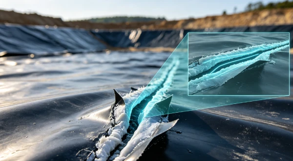
A fishmouth is a V-shaped or U-shaped notch at the edge of a welded seam, typically occurring at weld terminations, T-junctions, or seam intersections. The defect resembles a fish’s open mouth, hence the name. It represents a region where the seam has not achieved full fusion.
Q2: Why do fishmouth defects form?
Fishmouths form when panel geometry creates stress concentrations during welding. Common causes include: intersecting seams at acute angles, inadequate overlap at T-junctions, thermal contraction during weld cooling, panel misalignment, and improper welding sequence.
Q3: How do fishmouths affect seam integrity?
Fishmouths reduce effective weld width by 30–50% at the defect location. The V-shaped notch creates a stress concentration factor of 3–10x, initiating ESC within 2–5 years. Weld strength at fishmouth locations is typically 40–60% of full weld strength.
Q4: Where are fishmouth defects most commonly found?
Fishmouths are most common at: T-junctions (intersection of three panels), weld terminations (start/end of weld runs), intersections of seams at acute angles (< 60°), corners of panels, and locations where thermal contraction has created stress during welding.
Q5: What is the maximum acceptable fishmouth notch depth?
The maximum acceptable fishmouth notch depth is 5mm for most installations. Notches > 5mm require repair by patching. Notches > 10mm require section replacement. Any fishmouth with visible separation or incomplete fusion is unacceptable.
Q6: Can fishmouth defects be repaired?
Small fishmouths (< 5mm depth) can be repaired by extrusion welding over the defect. Larger fishmouths (> 5mm depth) require patching with a rounded patch (radius ≥ 1m) or section replacement. Repair procedures must follow GRI-GM19 guidelines.
Q7: How can fishmouths be prevented during installation?
Prevention requires: proper panel layout with 3–5m offset at T-junctions, corner radii ≥ 1m, welding sequence that minimises thermal stress, adequate overlap (≥ 150mm), and careful panel alignment during deployment.
Q8: What is the relationship between fishmouths and ESC?
Fishmouth notches create stress concentrations of 3–10x, exceeding the ESC threshold (2–5 MPa) and initiating crack growth. The notch geometry traps chemicals and moisture, accelerating ESC. Fishmouth-induced ESC typically occurs within 2–5 years.
Q9: How should fishmouth defects be documented during CQA?
All fishmouth defects should be photographed with scale reference, with location marked on as-built drawings. Notch depth, angle, and orientation should be recorded. Repair or replacement actions must be documented with photographs.
Q10: What CQA requirements address fishmouth prevention?
CQA requirements include: review of panel layout drawings, 100% visual inspection of all weld intersections, destructive testing targeting fishmouth locations, photographic documentation of all defects, and verification of repair procedures.
3️⃣ Why HDPE Is Used — Material Science Focus
HDPE dominates containment liner applications due to its excellent chemical resistance, low permeability, high tensile strength, and weldability. However, seam defects such as fishmouths can compromise long-term performance through stress concentration and ESC initiation.
Weldability and Seam Integrity: HDPE thermal welding creates a monolithic bond when performed correctly. However, fishmouth defects create regions of incomplete fusion where the weld has not fully penetrated. These regions have reduced strength and create stress concentrations.
Stress Crack Resistance (NCTL per ASTM D5397): ESC resistance is measured by the Notched Constant Tensile Load test. GRI-GM13 requires NCTL ≥ 500 hours. However, fishmouth notches create stress intensity factors that can overcome even high-NCTL resins. Resins with NCTL ≥ 1000 hours provide greater margin against fishmouth-induced ESC.
Tensile Modulus and Weld Stress: HDPE tensile modulus (E ≈ 800–1000 MPa) determines the stress concentration at fishmouth notches. Thermal contraction during weld cooling creates residual stress that is concentrated at fishmouth notches. Thicker liners (2.5mm) generate higher residual stress and are more susceptible to fishmouth-induced ESC.
Oxidative Induction Time (OIT vs HP-OIT): Fishmouths accelerate oxidation through stress-enhanced oxidation. HP-OIT monitoring (ASTM D5885) of fishmouth locations typically shows 2–3x faster depletion than defect-free seam areas. This means fishmouths can reduce the effective service life of the seam at that location.
Thermal Expansion and Contraction: HDPE CTE of 0.2 mm/m/°C means seams are subjected to cyclic thermal stress. Fishmouth notches concentrate this stress, making them the most common location for thermal-induced seam failure.
Carbon Black Content: Carbon black (2–3%) provides UV protection but does not prevent fishmouth formation. Proper dispersion (ASTM D5596 rating ≥ 1) ensures uniform weldability and resistance to stress cracking at fishmouth locations.
Alternatives Comparison: HDPE vs Other Liner Materials for Seam Quality
| Property | HDPE | LLDPE | fPP | PVC | GCL |
|---|---|---|---|---|---|
| Fishmouth tendency | Moderate to High | Moderate to High | Moderate | Low | N/A |
| Fishmouth stress concentration | 3–10x | 3–10x | 2–5x | 1–2x | N/A |
| Weld integrity at fishmouth | 40–60% of full | 40–60% of full | 50–70% of full | Not applicable | N/A |
| Fishmouth repair difficulty | Moderate | Moderate | Low | Low | N/A |
| ESC susceptibility at fishmouth | High (requires NCTL) | Moderate | Moderate | High | N/A |
| Field weldability | Excellent | Excellent | Fair | Good (solvent) | N/A |
| Cost relative to HDPE | 1.0x | 1.0–1.1x | 1.5–2.0x | 1.2–1.5x | 0.6–0.8x |
4️⃣ Fishmouth Formation Mechanisms
Understanding fishmouth formation is essential for prevention. Fishmouths form when panel geometry, welding sequence, and thermal stress combine to create stress concentrations at seam intersections.
Primary Fishmouth Formation Mechanisms:
- Intersecting seams at acute angles: When two seams meet at an angle less than 60°, the weld cannot follow the geometry without creating a notch. The V-shaped gap at the intersection creates the fishmouth defect.
- Inadequate overlap at T-junctions: At T-junctions (three panels meeting), inadequate overlap creates stress concentrations at the intersection point. The weld must change direction abruptly, creating a fishmouth at the transition.
- Thermal contraction during weld cooling: As the weld cools, thermal contraction creates residual stress. This stress is concentrated at seam intersections, forming fishmouths as the weld pulls away from the intersection.
- Panel misalignment: When panels are not properly aligned during deployment, the seam must accommodate misalignment by creating a notch. This notch becomes a fishmouth defect.
- Improper welding sequence: Welding sequence affects thermal stress distribution. If adjacent seams are welded in the wrong order, thermal contraction can create fishmouths at intersections.
- Panel geometry: Sharp corners (radius < 1m) create stress concentrations that form fishmouths at the corner intersection.
Fishmouth Geometry Characteristics:
| Characteristic | Typical Measurement | Impact on Performance |
|---|---|---|
| Notch depth | 2–20mm | Deeper = higher stress concentration |
| Notch angle | 20–90° | Smaller angle = higher stress concentration |
| Notch radius | < 1mm (sharp) | Sharp = ESC initiation |
| Effective weld width reduction | 30–50% | Reduced strength at defect |
Fishmouth Formation Locations:
| Location | Frequency | Severity |
|---|---|---|
| T-junctions (three panels) | Very High | High |
| Weld terminations (start/end) | High | Moderate |
| Acute angle intersections (< 60°) | High | Very High |
| Panel corners (radius < 1m) | Moderate | High |
| Seam intersections at slopes | Moderate | High |
5️⃣ Stress Concentration and Damage Mechanisms
Fishmouth defects create stress concentrations that initiate multiple damage mechanisms. Understanding these mechanisms explains why fishmouths are so damaging to long-term seam performance.
Stress Concentration at Fishmouth Notch:
- Applied stress: 1–2 MPa (typical service stress from loading)
- Stress concentration factor: 3–10x
- Local stress: 3–20 MPa (approaches or exceeds ESC threshold)
- Local stress at sharp notches: 15–60 MPa (exceeds yield stress)
Damage Mechanisms from Fishmouth Stress:
- Environmental Stress Cracking (ESC): Local stress exceeds ESC threshold (2–5 MPa). Chemical environment (leachate, surfactants) accelerates crack growth. Cracks initiate at fishmouth notch tip and propagate along the weld interface or through the base material.
- Reduced Weld Integrity: Fishmouth defects represent regions of incomplete fusion. The effective weld width is reduced by 30–50%, reducing the load-bearing capacity of the seam at that location.
- Stress-Enhanced Oxidation: Local stress reduces activation energy for oxidation. Oxidation rate increases by 2–3x at fishmouth notches. HP-OIT depletes faster at fishmouth locations than defect-free seam areas.
- Thermal Fatigue: Cyclic temperature changes cause expansion and contraction of the seam. The notch geometry concentrates this cyclic stress, causing fatigue damage and crack propagation.
- Moisture and Chemical Trapping: The fishmouth notch geometry traps moisture and chemicals, creating a local environment that accelerates degradation and ESC.
Stress Concentration Factors by Fishmouth Geometry:
| Fishmouth Depth | Notch Angle | Stress Concentration Factor | Local Stress (MPa)* |
|---|---|---|---|
| < 3mm | > 60° | 2–4x | 2–8 MPa |
| 3–5mm | 45–60° | 4–7x | 4–14 MPa |
| 5–10mm | 30–45° | 7–10x | 7–20 MPa |
| > 10mm | < 30° | 10–20x | 10–40 MPa |
*Based on applied stress of 1–2 MPa
6️⃣ Weld Integrity Reduction at Fishmouths
Fishmouth defects reduce the effective weld width and strength at the defect location. This section quantifies the reduction in seam performance.
Effective Weld Width Reduction:
| Fishmouth Type | Effective Weld Width | Strength Reduction |
|---|---|---|
| No defect (full weld) | 100% | 0% |
| Minor fishmouth (< 3mm) | 70–80% | 20–30% |
| Moderate fishmouth (3–5mm) | 50–70% | 30–50% |
| Severe fishmouth (> 5mm) | < 50% | > 50% |
Weld Strength at Fishmouth Locations:
| Parameter | Full Weld | Fishmouth Location | Reduction |
|---|---|---|---|
| Peel strength | ≥ 150 N/25mm | 60–100 N/25mm | 40–60% |
| Shear strength | ≥ 200 N/25mm | 80–140 N/25mm | 30–60% |
| Tensile strength | ≥ 20 MPa | 10–15 MPa | 25–50% |
| Elongation at break | ≥ 400% | 100–200% | 50–75% |
Failure Mode at Fishmouth Locations:
| Failure Mode | Frequency at Fishmouth | Description |
|---|---|---|
| Adhesive failure (peeling) | High | Weld separates at the interface |
| Cohesive failure (stretching) | Low | Material fails outside weld zone |
| ESC crack initiation | Very High | Cracks initiate at notch tip |
| Progressive failure | High | Cracks propagate from fishmouth |
Destructive Testing at Fishmouth Locations:
GRI-GM19 requires destructive testing at a frequency of one sample per 150m of seam length. CQA programs should target fishmouth locations for destructive testing.
| Test Type | Acceptance Criteria at Fishmouth | Action if Failed |
|---|---|---|
| Peel strength | ≥ 100 N/25mm | Repair or section replacement |
| Shear strength | ≥ 140 N/25mm | Repair or section replacement |
| Visual inspection | No visible defects | Section replacement |
7️⃣ Fishmouth Effects on Long-Term Performance
Fishmouth defects have cascading effects on long-term seam performance, reducing service life and increasing failure risk.
Performance Impact Summary:
| Performance Parameter | Impact of Fishmouth | Quantification |
|---|---|---|
| ESC resistance | Significantly reduced | 2–5x faster crack initiation |
| Effective weld width | Reduced | 30–50% reduction |
| Weld strength | Reduced | 40–60% reduction |
| Oxidation resistance | Accelerated | 2–3x faster HP-OIT depletion |
| Service life at fishmouth | Reduced | 50–80% reduction |
| Leak risk | Increased | 3–5x higher at fishmouths |
| Thermal stress resistance | Reduced | 2–3x higher failure rate |
Failure Timeline with Fishmouths:
| Time Since Installation | Failure Mechanism | Probability |
|---|---|---|
| 0–2 years | Installation defects at fishmouth | Low (CQA catches most) |
| 2–5 years | ESC initiation at fishmouth | Moderate (30–50% of fishmouth failures) |
| 5–10 years | ESC propagation through seam | High (70–90% of fishmouth failures) |
| 10–20 years | Combined degradation | Very High (all fishmouth failures) |
| > 20 years | Seam failure inevitable | Failure inevitable |
Cumulative Failure Probability:
| Fishmouth Severity | 10-year Failure Risk | 20-year Failure Risk |
|---|---|---|
| No fishmouths | 1–2% | 3–5% |
| Minor (< 3mm) | 5–10% | 15–25% |
| Moderate (3–5mm) | 15–25% | 40–60% |
| Severe (> 5mm) | 30–50% | 70–90% |
Leak Location Survey Findings:
| Application | Fishmouth Leaks | All Other Leaks |
|---|---|---|
| Landfills | 20–30% | 70–80% |
| Heap Leach Pads | 15–25% | 75–85% |
| Wastewater Lagoons | 25–35% | 65–75% |
| Tailings Facilities | 15–20% | 80–85% |
8️⃣ Real Engineering Failure Cases
Case 1: Fishmouth-Induced ESC — US Northeast Landfill, 2018
Specification used: 2.0mm HDPE, NCTL = 600 hours (GRI-GM13 minimum). T-junctions welded with inadequate overlap. Multiple fishmouth defects at T-junctions.
Observed failure: ESC cracks initiated at fishmouth notch tips after 3 years. Cracks propagated along weld interface. Leakage through T-junction seams. Six fishmouth locations with through-holes.
Timeline:
2018: 2.0mm HDPE installed, fishmouths at T-junctions
2018-2021: Thermal cycling, leachate exposure
2021: ESC cracks at fishmouth notch tips
2021-2022: Cracks propagated through T-junctions
2022: Leakage at six T-junction locations
Repair cost: $2.2M (section replacement + remediation)
Root cause: Inadequate overlap at T-junctions created fishmouth defects with notch depths of 5–8mm. The resin’s NCTL of 600 hours was insufficient to resist stress crack propagation under the stress concentration at fishmouth notches.
Engineering lesson: Provide 3–5m offset at T-junctions to prevent fishmouth formation. Specify NCTL ≥ 1000 hours for critical applications. Target fishmouth locations for destructive testing.
Case 2: Fishmouth-Accelerated Oxidation — Australian Mining Tailings Dam, 2019
Specification used: 2.0mm HDPE, HP-OIT initial = 430 minutes. Acute angle seam intersections (< 45°) created fishmouth defects. Surface temperature 65°C.
Observed failure: HP-OIT at fishmouth locations after 4 years measured 70 minutes (84% depletion). Surface cracking at fishmouth notches. Leakage through fishmouth locations. Non-fishmouth seam areas showed HP-OIT of 190 minutes (56% depletion).
Timeline:
2019: 2.0mm HDPE installed, fishmouths at acute angle intersections
2019-2023: Surface temp 65°C, stress concentration at fishmouths
2023: HP-OIT at fishmouth: 70min, non-fishmouth: 190min
2023: Surface cracking at fishmouths, leakage detected
2023: Section replacement at fishmouth locations
Repair cost: $1.9M (section replacement + monitoring)
Root cause: Acute angle seam intersections (< 45°) created fishmouth defects with sharp notches. Stress concentration accelerated oxidation by 2–3x at fishmouth locations. HP-OIT depletion at fishmouths was 84% versus 56% in non-fishmouth areas.
Engineering lesson: Avoid seam intersections at angles < 60°. Design panel layout with 3–5m offsets at T-junctions. HP-OIT monitoring should sample fishmouth locations separately.
Case 3: Fishmouth-Initiated Seam Failure — South African Heap Leach Pad, 2020
Specification used: 2.0mm HDPE. Fishmouth defects at weld terminations (start/end points). Inadequate welding procedure at terminations.
Observed failure: Seam failure at weld terminations after 18 months. Cracks propagated from fishmouth notches along the weld interface. Leakage through termination points.
Timeline:
2020: 2.0mm HDPE installed, fishmouths at weld terminations
2020-2021: Leachate exposure, thermal cycling
2021: Seam failure at termination points
2021: Leakage at termination locations
2021: Repair with extrusion welding patches
Repair cost: $1.0M (repairs + monitoring)
Root cause: Inadequate welding procedure at weld terminations created fishmouth defects at start/end points. The welding operator did not properly manage the termination, leaving a V-shaped notch. Thermal contraction and leachate exposure initiated ESC at the notch tips.
Engineering lesson: Implement proper weld termination procedures (taper or return weld) to prevent fishmouth formation. Training for welding operators on termination techniques. 100% visual inspection of weld terminations.
Failure Case Cost Summary
| Case | Location | Failure Mode | Cost | Primary Lesson |
|---|---|---|---|---|
| Case 1 | US Northeast | ESC at T-junction fishmouths | $2.2M | 3-5m offset at T-junctions, NCTL ≥ 1000h |
| Case 2 | Australia | Oxidation at acute angles | $1.9M | Avoid seams < 60°, HP-OIT monitor fishmouths |
| Case 3 | South Africa | Termination fishmouths | $1.0M | Proper termination procedures, visual inspection |
9️⃣ Comparison With Alternative Liner Systems
| Property | HDPE (2.0mm) | LLDPE (1.5mm) | PVC (1.5mm) | EPDM (1.5mm) | GCL |
|---|---|---|---|---|---|
| Fishmouth tendency | Moderate to High | Moderate to High | Low | Moderate | N/A |
| Fishmouth stress concentration | 3–10x | 3–10x | 1–2x | 1–2x | N/A |
| Weld integrity at fishmouth | 40–60% of full | 40–60% of full | Not applicable | Not applicable | N/A |
| Fishmouth repair difficulty | Moderate | Moderate | Low | Low | N/A |
| ESC susceptibility at fishmouth | High (requires NCTL) | Moderate | High | Moderate | N/A |
| Oxidation acceleration at fishmouth | 2–3x | 2–3x | 1–2x | 1–2x | N/A |
| Thermal stress resistance at fishmouth | Reduced | Reduced | Fair | Fair | N/A |
| Field weldability | Excellent | Excellent | Good (solvent) | Poor | N/A |
| Containment application suitability | ✅ Recommended (with fishmouth prevention) | ⚠️ Limited | ❌ Not recommended | ⚠️ Limited (cost) | ✅ Composite use |
| Cost relative to HDPE | 1.0x | 1.0–1.1x | 1.2–1.5x | 2.0–3.0x | 0.6–0.8x |
Table scrolls horizontally on mobile
🔟 Fishmouth Prevention and CQA Requirements
Fishmouth prevention is the most effective strategy for long-term seam performance. Prevention is significantly less costly than repair or remediation.
Panel Layout Design Requirements:
- ✅ T-junction offset: Minimum 3–5m offset between adjacent seams to prevent stress concentration
- ✅ Seam angles: Avoid seam intersections at angles < 60°
- ✅ Corner radius: Minimum 1m radius for all panel corners
- ✅ Seam spacing: Minimum 1m between parallel seams
- ✅ Termination details: Taper or return weld at all seam terminations
Welding Procedures to Prevent Fishmouths:
| Measure | Implementation | Effectiveness |
|---|---|---|
| Proper welding sequence | Weld from centre outward to distribute stress | High |
| Adequate overlap | Minimum 150mm overlap at T-junctions | High |
| Termination taper | Taper weld at ends to reduce stress | High |
| Corner radius | Minimum 1m radius at corners | High |
| Preheating | For cold weather welding (< 5°C) | Moderate |
Fishmouth Acceptance Criteria:
| Parameter | Acceptance Criteria |
|---|---|
| Maximum notch depth | < 5mm |
| Notch angle | > 60° |
| Notch radius | > 1mm |
| Visible separation | None |
| Fusion quality | Full fusion visible |
Fishmouth Rejection Criteria:
| Parameter | Rejection Criteria |
|---|---|
| Notch depth | > 5mm (repair required) |
| Notch depth | > 10mm (section replacement) |
| Sharp notch | Radius < 1mm |
| Visible separation | Any |
| Incomplete fusion | Any |
Fishmouth Repair Procedures:
| Repair Type | Application | Procedure |
|---|---|---|
| Extrusion patch | Notch < 5mm depth | Extrude weld over defect |
| Round patch | Notch 5–10mm depth | Round patch (radius ≥ 1m) over fishmouth |
| Section replacement | Notch > 10mm depth | Replace entire section |
CQA Requirements for Fishmouth Prevention:
- ✅ Pre-installation: Review panel layout drawings, verify T-junction offsets
- ✅ During welding: 100% visual inspection of all weld intersections
- ✅ Fishmouth detection: Document all fishmouths with photographs and scale reference
- ✅ Fishmouth repair: Document repair procedures with photographs
- ✅ Destructive testing: Target fishmouth locations for destructive testing
- ✅ Documentation: All photographs, measurements, and repairs retained
1️⃣1️⃣ Professional Engineering Recommendation
Fishmouth Risk Management Matrix:
| Fishmouth Risk Level | Panel Layout | Welding Procedure | Acceptance Criteria | Action on Detection |
|---|---|---|---|---|
| Low: Simple panels, no T-junctions | Standard layout | Standard welding | Notch < 5mm | Repair if > 3mm |
| Moderate: T-junctions present | 3m offset at T-junctions | Enhanced sequence | Notch < 3mm | Repair if > 3mm |
| High: Multiple T-junctions, acute angles | 5m offset, avoid < 60° | Critical sequence | Notch < 2mm | Section replacement if > 3mm |
| Extreme: Complex geometry, critical application | Specialist layout design | Specialist procedure | No fishmouths | Section replacement |
When to Specify Enhanced Fishmouth Prevention:
- Complex panel layouts with multiple T-junctions
- Critical containment (hazardous waste, groundwater protection)
- Design life > 50 years
- High-stress applications (deep landfills > 30m)
- Limited post-installation access for monitoring
- Aggressive chemical environment (VOCs, surfactants)
Quality Assurance Requirements:
- ✅ Panel layout review: Independent verification of T-junction offsets and corner radii
- ✅ Welding procedure review: Verification of termination procedures
- ✅ Fishmouth inspection: 100% visual inspection with photographic documentation
- ✅ Destructive testing: Target fishmouth locations at 150m intervals
- ✅ Repair verification: Independent inspection of all repairs
- ✅ Documentation retention: All records for lifetime of facility
1️⃣2️⃣ FAQ Section
Q1: What is a fishmouth defect in HDPE seams?
A fishmouth is a V-shaped or U-shaped notch at the edge of a welded seam, typically occurring at weld terminations, T-junctions, or seam intersections. The defect resembles a fish’s open mouth and represents a region where the seam has not achieved full fusion.
Q2: Why do fishmouth defects form?
Fishmouths form when panel geometry creates stress concentrations during welding. Common causes include: intersecting seams at acute angles, inadequate overlap at T-junctions, thermal contraction during weld cooling, panel misalignment, and improper welding sequence.
Q3: How do fishmouths affect seam integrity?
Fishmouths reduce effective weld width by 30–50% at the defect location. The V-shaped notch creates a stress concentration factor of 3–10x, initiating ESC within 2–5 years. Weld strength at fishmouth locations is typically 40–60% of full weld strength.
Q4: Where are fishmouth defects most commonly found?
Fishmouths are most common at: T-junctions (intersection of three panels), weld terminations (start/end of weld runs), intersections of seams at acute angles (< 60°), corners of panels, and locations where thermal contraction has created stress during welding.
Q5: What is the maximum acceptable fishmouth notch depth?
The maximum acceptable fishmouth notch depth is 5mm for most installations. Notches > 5mm require repair by patching. Notches > 10mm require section replacement. Any fishmouth with visible separation or incomplete fusion is unacceptable.
Q6: Can fishmouth defects be repaired?
Small fishmouths (< 5mm depth) can be repaired by extrusion welding over the defect. Larger fishmouths (> 5mm depth) require patching with a rounded patch (radius ≥ 1m) or section replacement. Repair procedures must follow GRI-GM19 guidelines.
Q7: How can fishmouths be prevented during installation?
Prevention requires: proper panel layout with 3–5m offset at T-junctions, corner radii ≥ 1m, welding sequence that minimises thermal stress, adequate overlap (≥ 150mm), and careful panel alignment during deployment.
Q8: What is the relationship between fishmouths and ESC?
Fishmouth notches create stress concentrations of 3–10x, exceeding the ESC threshold (2–5 MPa) and initiating crack growth. The notch geometry traps chemicals and moisture, accelerating ESC. Fishmouth-induced ESC typically occurs within 2–5 years.
Q9: How should fishmouth defects be documented during CQA?
All fishmouth defects should be photographed with scale reference, with location marked on as-built drawings. Notch depth, angle, and orientation should be recorded. Repair or replacement actions must be documented with photographs.
Q10: What CQA requirements address fishmouth prevention?
CQA requirements include: review of panel layout drawings, 100% visual inspection of all weld intersections, destructive testing targeting fishmouth locations, photographic documentation of all defects, and verification of repair procedures.
1️⃣3️⃣ Technical Conclusion
Fishmouth defects are among the most common and damaging seam defects in HDPE geomembrane installations, responsible for 20–30% of all detected leaks and a significant proportion of seam failures. The stress concentration at fishmouth notches (3–10x) creates local stresses that exceed ESC thresholds and initiate crack growth within 2–5 years of installation. The effective weld width at fishmouth locations is reduced by 30–50%, and weld strength is reduced by 40–60%.
Prevention through proper panel layout and welding procedure is the most effective strategy. T-junctions must have 3–5m offset between adjacent seams, seam intersections at angles < 60° must be avoided, and corner radii must be ≥ 1m. Welding sequence must be managed to minimise thermal stress concentration at intersections. Weld terminations must be tapered or returned to prevent fishmouth formation.
CQA programs must include 100% visual inspection of all weld intersections, with photographic documentation of all fishmouth defects. Destructive testing should target fishmouth locations at the required frequency of one sample per 150m of seam length. Fishmouths with notch depth > 5mm require repair; those > 10mm require section replacement.
Monitoring and documentation are essential for long-term performance assessment. HP-OIT testing should sample fishmouth locations separately, as oxidation accelerates 2–3x faster at fishmouths. Leak location surveys should focus on T-junctions and seam intersections where fishmouths are most likely. All installation documentation, including fishmouth photographs and repair records, should be retained for the lifetime of the facility.
Lifecycle cost analysis consistently demonstrates that fishmouth prevention is cost-effective. The cost of proper panel layout, welding procedure, and CQA ($5,000–20,000 per installation) is far lower than failure remediation ($500,000–5,000,000). Fishmouth prevention, panel layout design, and rigorous CQA are the most cost-effective tools available for ensuring long-term seam performance.
📚 Related Technical Guides
HDPE Geomembrane Seam Welding: A CQA Engineer's Field Manual for Fishmouth PreventionPanel Layout Design for Geomembrane Installations: T-Junction and Corner GeometryWeld Termination Procedures: Taper and Return Welding TechniquesFishmouth Defect Repair: Extrusion Welding and Patching ProceduresHDPE Geomembrane Failure Investigation: Fishmouth-Related Root Cause Analysis