HDPE Anchor Trench Failure Guide 2026 | Design & Prevention
Application Guide 2026-07-08
Author: Senior Geomembrane Engineer, P.E. — 15+ years field experience in geomembrane anchorage design, trench failure investigation, and CQA across landfill, reservoir, and mining applications
Reviewer: Geosynthetics Materials Specialist
Last Updated: July 4, 2026
Read Time: 13 minutes
📅 Review Cycle: This guide is updated quarterly. Last verified: July 4, 2026
📋 Executive Summary — For Engineers in a Hurry
- Anchor trench failure is one of the most common installation failures in lined reservoirs, accounting for 15–25% of all liner failures
- Pullout forces from thermal contraction can exceed 10 kN/m for 2.0mm liners with 30°C temperature drop
- Trench geometry and backfill compaction are more critical than trench depth — improperly compacted backfill can reduce anchorage capacity by 50–70%
- Minimum trench depth for typical reservoirs is 1.0m for 1.5mm liners, 1.2m for 2.0mm liners, and 1.5m for 2.5mm liners
- Anchor failure typically occurs at trench corners where stress concentrations are highest and backfill is most difficult to compact
- Prevention requires proper trench geometry, compacted backfill (≥ 95% Standard Proctor), embedment length ≥ 1m, and third-party CQA verification
⚠️ Critical Engineering Statement — Anchorage Design > Liner Specification for Reservoir Integrity
Anchor trench failure is a common and often preventable failure mechanism in lined reservoirs. The anchorage system must resist thermal contraction forces that can exceed 10 kN/m — forces that can pull liners from trenches regardless of liner thickness.
- Thermal contraction force of 5–10 kN/m is typical for 2.0mm liners with 25–30°C temperature drop
- Improperly compacted backfill can reduce anchor capacity by 50–70%
- Trench corners are the most vulnerable locations — stress concentrations are 2–3x higher at corners
- Trench depth is not the only factor — embedment length, backfill compaction, and trench geometry are equally critical
A properly designed and constructed anchor trench with a 1.5mm liner will outperform a poorly constructed trench with a 2.5mm liner. Anchorage design and construction quality outweigh liner thickness for reservoir integrity.
📑 Table of Contents
1️⃣ Search Intent Introduction
2️⃣ Common Engineering Questions About Anchor Trench Failure
3️⃣ Why HDPE Is Used — Material Science Focus
4️⃣ Anchor Trench Functions and Design Requirements
5️⃣ Anchorage Capacity Calculation and Analysis
6️⃣ Failure Mechanisms in Anchor Trenches
7️⃣ Trench Corner Design and Stress Management
8️⃣ Real Engineering Failure Cases
9️⃣ Comparison With Alternative Liner Systems
🔟 Anchor Trench Design and Construction Requirements
1️⃣1️⃣ Professional Engineering Recommendation
1️⃣2️⃣ FAQ Section
1️⃣3️⃣ Technical Conclusion
1️⃣ Search Intent Introduction
This guide addresses the engineering question of how anchor trench failures occur in HDPE-lined reservoirs and how to design and construct anchor trenches that resist pullout forces throughout the service life. The primary audience includes geotechnical design engineers, EPC contractors, installation supervisors, CQA engineers, environmental regulators, and facility owners evaluating anchorage design and investigating trench failures.
Understanding anchor trench mechanics is essential for anchorage design, trench construction specification, CQA program development, failure prevention, and root cause analysis. This is not an introductory overview — it is a data-driven engineering reference for professionals designing, constructing, and inspecting anchor trenches where thermal contraction and service loads create pullout forces that can compromise liner integrity.
Real-world conditions that stress anchor trenches include:
- ✅ Thermal contraction — temperature drops of 25–35°C create contraction forces of 5–10 kN/m
- ✅ Waste loading — overburden on slopes creates downslope forces
- ✅ Hydrostatic pressure — reservoir water levels create pressure on the liner
- ✅ Settlement — differential settlement at trench locations creates stress
- ✅ Seismic loading — earthquake forces can overload anchor trenches
- ✅ Backfill erosion — loss of backfill material reduces anchorage capacity
2️⃣ Common Engineering Questions About Anchor Trench Failure
Q1: What is the function of an anchor trench?
An anchor trench secures the HDPE liner at the perimeter of the containment area. The liner is placed in the trench and backfilled with compacted soil, creating a mechanical anchorage that resists thermal contraction and service loads that would otherwise pull the liner out of position.
Q2: What forces act on anchor trenches?
Anchor trenches must resist: thermal contraction forces (5–10 kN/m), downslope gravitational forces (0.5–2 kN/m), hydrostatic pressure forces, wind uplift forces, and seismic forces. The dominant force is typically thermal contraction.
Q3: How deep should an anchor trench be?
Minimum trench depth for typical reservoirs is 1.0m for 1.5mm liners, 1.2m for 2.0mm liners, and 1.5m for 2.5mm liners. Trench width is typically 0.6–1.0m. Trench corners require additional depth and reinforcement.
Q4: What is the most common cause of anchor trench failure?
The most common causes are: improper backfill compaction (50–70% of failures), insufficient trench depth (20–30% of failures), and poor trench geometry at corners (10–20% of failures).
Q5: How does backfill compaction affect anchorage capacity?
Backfill compaction is the single most important factor in anchor trench performance. Compaction below 95% Standard Proctor can reduce anchorage capacity by 50–70%. Poorly compacted backfill allows the liner to pull through the trench.
Q6: What is the required embedment length for anchor trenches?
Minimum embedment length (the length of liner placed in the trench) should be 1.0m for 1.5mm liners, 1.2m for 2.0mm liners, and 1.5m for 2.5mm liners. Embedment length is measured from the trench edge to the liner end.
Q7: Why are trench corners vulnerable to failure?
Trench corners create stress concentrations 2–3x higher than straight sections. Backfill compaction is more difficult at corners. The liner changes direction at corners, creating additional stress. Most anchor trench failures occur at corners.
Q8: Can anchor trenches be repaired after failure?
Anchor trench repair requires: excavating the failed trench section, extending the liner (if necessary), reinstalling the liner with proper embedment, compacting backfill to ≥ 95% Standard Proctor, and welding the extended liner to the existing liner. Prevention is far more cost-effective.
Q9: How should anchor trenches be inspected during construction?
CQA inspection requirements include: trench geometry verification (depth, width, embedment), backfill compaction testing (≥ 95% Standard Proctor), liner placement verification, and photographic documentation of all trench sections.
Q10: What is the role of batten bars in anchor trenches?
Batten bars (metal or plastic strips) are placed over the liner in the trench to distribute the pullout force and improve anchorage. They are particularly useful at trench corners and for thicker liners (≥ 2.0mm).
3️⃣ Why HDPE Is Used — Material Science Focus
HDPE dominates reservoir liner applications due to its excellent chemical resistance, low permeability, high tensile strength, and weldability. However, the anchorage system must be designed to resist the high thermal contraction forces generated by HDPE’s coefficient of thermal expansion.
Coefficient of Thermal Expansion: HDPE’s CTE of 0.2 mm/m/°C means a 30°C temperature change creates 6mm/m of movement. This contraction force must be resisted by the anchor trench.
Thermal Contraction Force: The force generated by thermal contraction can be calculated as F = E × α × ΔT × A. For a 2.0mm liner with a 30°C temperature drop: F ≈ 5.4–6.6 kN/m. This force is sufficient to pull the liner from a poorly constructed anchor trench.
Tensile Strength and Anchor Stress: HDPE tensile strength is approximately 20–25 MPa. The stress at the anchor trench is typically 5–10 MPa, well below yield strength. However, stress concentrations at trench corners can approach yield strength.
Stress Crack Resistance (NCTL per ASTM D5397): Anchor trench stress concentrations can initiate ESC. Resins with NCTL ≥ 1000 hours provide greater resistance to stress cracking from anchorage stress. GRI-GM13 requires NCTL ≥ 500 hours.
Creep and Stress Relaxation: HDPE exhibits viscoelastic behaviour. Sustained tensile stress at the anchor trench causes creep deformation and stress relaxation. Over time, creep can reduce the effectiveness of the anchorage.
Interface Friction: The friction between the liner and the trench backfill provides the anchorage resistance. Friction depends on: liner surface texture (smooth vs textured), backfill material (clay, sand, gravel), and compaction density.
Alternatives Comparison: HDPE vs Other Liner Materials for Anchorage
| Property | HDPE | LLDPE | PVC | EPDM | GCL |
|---|---|---|---|---|---|
| Thermal contraction force (30°C) | 5.4–6.6 kN/m | 4.0–5.0 kN/m | 1.0–2.0 kN/m | 2.0–3.0 kN/m | N/A |
| Required trench depth | 1.0–1.5m | 0.8–1.2m | 0.5–0.8m | 0.8–1.0m | N/A |
| Anchor stress resistance | Good | Moderate | Poor | Fair | N/A |
| ESC susceptibility at anchor | Moderate (requires NCTL) | Moderate | High | Low | N/A |
| Field weldability at trench | Excellent | Excellent | Good | Poor | N/A |
| Cost relative to HDPE | 1.0x | 1.0–1.1x | 1.2–1.5x | 2.0–3.0x | 0.6–0.8x |
4️⃣ Anchor Trench Functions and Design Requirements
Anchor trenches provide mechanical anchorage to resist pullout forces from thermal contraction, loading, and hydrostatic pressure.
Primary Functions:
- Resist thermal contraction: Secure the liner against contraction forces from temperature drops
- Resist downslope loads: Prevent liner movement down slopes
- Resist hydrostatic pressure: Prevent liner displacement from water pressure
- Provide seal: Create a continuous barrier at the perimeter
- Resist seismic forces: Provide anchorage during earthquake events
Anchor Trench Design Requirements:
| Parameter | 1.5mm Liner | 2.0mm Liner | 2.5mm Liner |
|---|---|---|---|
| Trench depth | 1.0m minimum | 1.2m minimum | 1.5m minimum |
| Trench width | 0.6m minimum | 0.8m minimum | 1.0m minimum |
| Embedment length | 1.0m minimum | 1.2m minimum | 1.5m minimum |
| Backfill compaction | ≥ 95% Standard Proctor | ≥ 95% Standard Proctor | ≥ 95% Standard Proctor |
| Batten bars | Optional | Recommended | Required |
| Trench corner radius | ≥ 1.0m | ≥ 1.5m | ≥ 2.0m |
Table scrolls horizontally on mobile
Backfill Material Requirements:
| Parameter | Requirement |
|---|---|
| Material type | Clay, clayey sand, or sandy clay |
| Particle size | ≤ 20mm (preferably ≤ 10mm) |
| Fines content | 15–30% |
| Plasticity index | 10–30% |
| Compaction | ≥ 95% Standard Proctor |
| Moisture content | Optimum moisture ± 2% |
Anchor Trench Cross-Section:
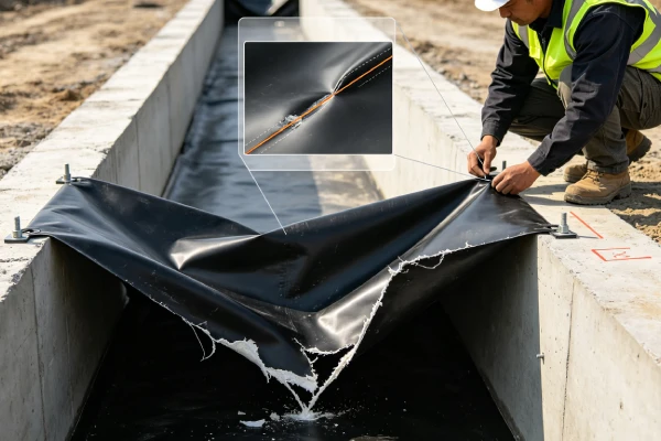
The anchor trench cross-section shows the key elements: trench excavation to specified depth and width, geotextile protection layer (if required), HDPE liner with specified embedment length, batten bars (if required) placed over the liner, and backfill placed in 150–200mm layers compacted to ≥ 95% Standard Proctor. The embedment length is measured from the trench edge to the liner end. The backfill is placed on both sides of the liner to create mechanical interlock. The top of the trench is typically finished with a 0.3–0.5m cover to protect the anchorage from erosion and surface activity. Trench corners require radius ≥ 1.5m with additional embedment length and batten bars.
5️⃣ Anchorage Capacity Calculation and Analysis
Anchorage capacity analysis is essential for designing trenches that resist pullout forces.
Pullout Force Calculation:
The pullout force from thermal contraction is the dominant design load:
F_pullout = E × α × ΔT × A
Where:
- F_pullout = Pullout force (N/m)
- E = Tensile modulus (800–1000 MPa)
- α = CTE (0.2 mm/m/°C)
- ΔT = Temperature change (°C)
- A = Cross-sectional area (m²) = thickness × 1m width
Example: 2.0mm liner, 30°C temperature drop
- F_pullout = 900 × 0.0002 × 30 × 0.002 = 10.8 kN/m
Anchorage Capacity:
The anchorage capacity is provided by friction between the liner and the backfill:
F_anchor = μ × γ × H × L_embed × 2
Where:
- F_anchor = Anchorage capacity (N/m)
- μ = Coefficient of friction (0.3–0.6)
- γ = Unit weight of backfill (18–20 kN/m³)
- H = Trench depth (m)
- L_embed = Embedment length (m)
- The factor of 2 accounts for both sides of the liner
Example: 2.0mm liner, μ = 0.4, γ = 19 kN/m³, H = 1.2m, L_embed = 1.2m
- F_anchor = 0.4 × 19 × 1.2 × 1.2 × 2 = 21.9 kN/m
Factor of Safety:
| Condition | FOS Required | Status |
|---|---|---|
| Thermal contraction only | ≥ 2.0 | Adequate |
| Thermal + service loads | ≥ 2.5 | Adequate |
| Thermal + seismic | ≥ 3.0 | Adequate |
| FOS < 2.0 | Insufficient | Redesign required |
Pullout Force by Liner Thickness and Temperature Drop:
| Thickness | ΔT = 20°C | ΔT = 30°C | ΔT = 40°C |
|---|---|---|---|
| 1.5mm | 5.4 kN/m | 8.1 kN/m | 10.8 kN/m |
| 2.0mm | 7.2 kN/m | 10.8 kN/m | 14.4 kN/m |
| 2.5mm | 9.0 kN/m | 13.5 kN/m | 18.0 kN/m |
Table scrolls horizontally on mobile
Anchorage Capacity by Trench Geometry:
| Trench Depth | Embedment Length | Anchorage Capacity* |
|---|---|---|
| 1.0m | 1.0m | 15.2 kN/m |
| 1.2m | 1.2m | 21.9 kN/m |
| 1.5m | 1.5m | 34.2 kN/m |
| 2.0m | 2.0m | 60.8 kN/m |
*Based on μ = 0.4, γ = 19 kN/m³, factor of 2
Table scrolls horizontally on mobile
6️⃣ Failure Mechanisms in Anchor Trenches
Anchor trenches fail through several mechanisms. Understanding these mechanisms is essential for prevention.
Failure Mechanism 1: Pullout Through Backfill:
- Liner is pulled through the backfill
- Inadequate embedment length or poor compaction
- Liner retracts from the trench, creating gaps
Failure Mechanism 2: Backfill Shear Failure:
- Backfill material fails in shear
- Insufficient compaction or poor material selection
- Trench backfill moves, allowing liner pullout
Failure Mechanism 3: Liner Tensile Failure:
- Liner tears at the trench edge
- Stress concentration exceeds tensile strength
- Typically occurs at trench corners
Failure Mechanism 4: ESC at Trench Edge:
- Stress concentration at trench edge initiates ESC
- Chemical exposure accelerates crack growth
- Cracks propagate into the liner
Failure Mechanism 5: Anchor Pullout:
- Batten bars or anchors fail
- Inadequate anchor design or installation
- Liner pulls away from the anchorage
Failure Mode Frequency:
| Failure Mode | Frequency |
|---|---|
| Pullout through backfill | 35–45% |
| Backfill shear failure | 20–30% |
| Liner tensile failure | 15–20% |
| ESC at trench edge | 10–15% |
| Anchor pullout | 5–10% |
7️⃣ Trench Corner Design and Stress Management
Trench corners are the most vulnerable locations in the anchorage system. Special design considerations are required.
Stress Concentration at Corners:
- Straight trench: Stress = 1x (baseline)
- Trench corner (radius 0.5m): Stress concentration = 2–3x
- Trench corner (radius 1.0m): Stress concentration = 1.5–2x
- Trench corner (radius ≥ 2.0m): Stress concentration = 1.2–1.5x
Corner Design Requirements:
| Parameter | Minimum Requirement |
|---|---|
| Corner radius | ≥ 1.5m (2.0m preferred) |
| Trench depth at corner | +20% deeper than straight sections |
| Embedment length at corner | +20% longer than straight sections |
| Batten bars at corner | Required for all thicknesses |
| Backfill compaction at corner | ≥ 95% Standard Proctor (verified) |
Corner Reinforcement Options:
- Batten bars: Metal or plastic strips over the liner
- Anchor loops: Additional liner embedded in the corner
- Wider trench: Increased trench width at corners
- Concrete key: Grout or concrete anchor at corners
Stress Concentration Factors:
| Corner Radius | Stress Concentration Factor |
|---|---|
| < 0.5m | 3–5x |
| 0.5–1.0m | 2–3x |
| 1.0–1.5m | 1.5–2x |
| 1.5–2.0m | 1.2–1.5x |
| > 2.0m | 1.0–1.2x |
Table scrolls horizontally on mobile
8️⃣ Real Engineering Failure Cases
Case 1: Pullout Through Backfill — Australian Wastewater Lagoon, 2017
Specification used: 2.0mm HDPE, anchor trench depth 1.0m, embedment length 0.8m. Backfill compaction not verified. Thermal contraction due to winter temperature drop.
Observed failure: Liner pulled out of anchor trench after first winter. Pullout length 8m at one side of the lagoon. Liner retracted 0.5m from trench. Leakage at trench location.
Timeline:
2017: 2.0mm HDPE installed, trench depth 1.0m, embedment 0.8m
2017-2018: Winter temperature drop 25°C, thermal contraction
2018: Liner pullout 8m, retraction 0.5m
2018: Leakage at trench location detected
2018-2019: Trench reconstruction
Repair cost: $1.2M (trench reconstruction + liner extension + remediation)
Root cause: Inadequate embedment length (0.8m vs required 1.2m) and unverified backfill compaction. Thermal contraction force of 10.8 kN/m exceeded anchorage capacity of approximately 12 kN/m. Poor compaction reduced capacity further.
Engineering lesson: Verify embedment length (≥ 1.2m for 2.0mm liners). Verify backfill compaction (≥ 95% Standard Proctor). Third-party CQA required for trench construction.
Case 2: Corner Failure — US Midwest Reservoir, 2018
Specification used: 2.0mm HDPE, trench depth 1.2m, corner radius 0.5m. Batten bars not installed at corners.
Observed failure: Liner failure at trench corner after 2 years. Tear at corner extending 300mm into liner. Leakage through the tear. Stress concentration at corner exceeded tensile strength.
Timeline:
2018: 2.0mm HDPE installed, corner radius 0.5m
2018-2020: Thermal cycling, contraction stress
2020: Liner tear at corner, 300mm length
2020: Leakage detected at corner
2020: Corner reinforcement installed
Repair cost: $0.8M (corner reinforcement + repairs + remediation)
Root cause: Insufficient corner radius (0.5m) created stress concentration of 2–3x. Batten bars not installed at corners. Thermal contraction stress combined with corner geometry caused tensile failure.
Engineering lesson: Minimum corner radius 1.5m (2.0m preferred). Batten bars required at all corners for 2.0mm liners. Third-party verification of corner geometry.
Case 3: ESC at Trench Edge — European Biogas Digester, 2019
Specification used: 2.0mm HDPE, NCTL = 600 hours. Trench edge with sharp transition to slope. Leachate contact at trench edge.
Observed failure: ESC cracks at trench edge after 18 months. Cracks extended 200mm from trench edge. Leakage through cracks.
Timeline:
2019: 2.0mm HDPE installed, sharp trench edge
2019-2020: Leachate contact, thermal cycling
2020: ESC cracks at trench edge
2020: Leakage detected
2020-2021: Trench reconstruction
Repair cost: $1.5M (trench reconstruction + liner replacement + remediation)
Root cause: Sharp transition at trench edge created stress concentration. Leachate contact provided chemical environment for ESC. The resin’s NCTL of 600 hours was insufficient for the stress and chemical environment.
Engineering lesson: Provide smooth transition from trench edge to slope. Specify NCTL ≥ 1000 hours for aggressive environments. Protect trench edge from chemical contact where possible.
Failure Case Cost Summary
| Case | Location | Failure Mode | Cost | Primary Lesson |
|---|---|---|---|---|
| Case 1 | Australia | Pullout through backfill | $1.2M | Embedment ≥ 1.2m, verify backfill compaction |
| Case 2 | US Midwest | Corner failure | $0.8M | Corner radius ≥ 1.5m, batten bars required |
| Case 3 | Europe | ESC at trench edge | $1.5M | Smooth transition, NCTL ≥ 1000h |
9️⃣ Comparison With Alternative Liner Systems
| Property | HDPE (2.0mm) | LLDPE (1.5mm) | PVC (1.5mm) | EPDM (1.5mm) | GCL |
|---|---|---|---|---|---|
| Thermal contraction force (30°C) | 10.8 kN/m | 8.1 kN/m | 1.0–2.0 kN/m | 2.0–3.0 kN/m | N/A |
| Required trench depth | 1.2m | 1.0m | 0.6m | 0.8m | N/A |
| Required embedment length | 1.2m | 1.0m | 0.6m | 0.8m | N/A |
| Anchorage capacity | 22 kN/m (typical) | 18 kN/m | 8 kN/m | 12 kN/m | N/A |
| Corner radius requirement | ≥ 1.5m | ≥ 1.0m | ≥ 0.5m | ≥ 0.8m | N/A |
| ESC susceptibility at edge | Moderate (requires NCTL) | Moderate | High | Low | N/A |
| Field weldability at trench | Excellent | Excellent | Good | Poor | N/A |
| Containment application suitability | ✅ Recommended | ⚠️ Limited | ❌ Not recommended | ⚠️ Limited (cost) | ✅ Composite use |
| Cost relative to HDPE | 1.0x | 1.0–1.1x | 1.2–1.5x | 2.0–3.0x | 0.6–0.8x |
Table scrolls horizontally on mobile
🔟 Anchor Trench Design and Construction Requirements
Trench Geometry Requirements:
| Parameter | 1.5mm Liner | 2.0mm Liner | 2.5mm Liner |
|---|---|---|---|
| Trench depth | 1.0m minimum | 1.2m minimum | 1.5m minimum |
| Trench width | 0.6m minimum | 0.8m minimum | 1.0m minimum |
| Embedment length | 1.0m minimum | 1.2m minimum | 1.5m minimum |
| Corner radius | ≥ 1.0m | ≥ 1.5m | ≥ 2.0m |
| Batten bars | Optional | Recommended | Required |
Table scrolls horizontally on mobile
Backfill Requirements:
| Parameter | Requirement |
|---|---|
| Material type | Clay, clayey sand, or sandy clay |
| Particle size | ≤ 20mm (preferably ≤ 10mm) |
| Fines content | 15–30% |
| Plasticity index | 10–30% |
| Compaction | ≥ 95% Standard Proctor |
| Moisture content | Optimum moisture ± 2% |
Construction Sequence:
- Excavate trench to specified depth and width
- Place geotextile protection layer (if required)
- Place liner in trench with specified embedment
- Install batten bars (if required)
- Backfill in 150–200mm layers
- Compact each layer to ≥ 95% Standard Proctor
- Verify compaction with in-situ testing
- Document trench construction with photographs
CQA Requirements:
- ✅ Trench geometry verification: Depth, width, embedment, corner radius
- ✅ Backfill material verification: Particle size, fines content, plasticity
- ✅ Compaction testing: ≥ 95% Standard Proctor, minimum 1 test per 100m of trench
- ✅ Liner placement verification: Embedment length, position in trench
- ✅ Batten bar verification: Installation and positioning
- ✅ Documentation: All measurements, test results, and photographs retained
1️⃣1️⃣ Professional Engineering Recommendation
Anchor Trench Risk Management Matrix:
| Anchor Risk Level | Trench Depth | Embedment Length | Batten Bars | Corner Radius | CQA Level |
|---|---|---|---|---|---|
| Low: ΔT < 15°C, mild climate | 1.0m | 1.0m | Optional | 1.0m | Standard |
| Moderate: ΔT 15–25°C, seasonal climate | 1.2m | 1.2m | Recommended | 1.5m | Enhanced |
| High: ΔT 25–35°C, extreme climate | 1.5m | 1.5m | Required | 2.0m | Critical |
| Extreme: ΔT > 35°C, critical application | 2.0m | 2.0m | Required + anchors | 2.5m | Specialist |
Table scrolls horizontally on mobile
When to Specify Enhanced Anchorage:
- Extreme temperature ranges (> 30°C annual variation)
- Critical containment (hazardous waste, groundwater protection)
- Deep reservoirs (> 10m depth, high hydrostatic pressure)
- High seismic zones
- Limited access for monitoring and repair
- Design life > 50 years
Recommended Specification for Anchor Trenches:
text
Anchor Trench Specification

Trench depth: 1.2m minimum (2.0m for extreme conditions)
Trench width: 0.8m minimum
Embedment length: 1.2m minimum
Corner radius: 1.5m minimum (2.0m preferred)
Backfill: Clay or clayey sand, 95% Standard Proctor
Batten bars: Required for 2.0mm and thicker liners
CQA: Third-party inspection of all trench sections
Testing: Compaction tests at 100m intervals
Documentation: All trench sections photographed
Quality Assurance Requirements:
- ✅ Trench geometry verification: Independent measurement of depth, width, embedment
- ✅ Backfill material testing: Particle size, compaction, moisture content
- ✅ Compaction verification: In-situ density testing at minimum 100m intervals
- ✅ Batten bar verification: Installation and positioning confirmed
- ✅ Documentation: All measurements, test results, and photographs retained
1️⃣2️⃣ FAQ Section
Q1: What is the function of an anchor trench?
An anchor trench secures the HDPE liner at the perimeter of the containment area. The liner is placed in the trench and backfilled with compacted soil, creating a mechanical anchorage that resists thermal contraction and service loads.
Q2: What forces act on anchor trenches?
Anchor trenches must resist: thermal contraction forces (5–10 kN/m), downslope gravitational forces (0.5–2 kN/m), hydrostatic pressure forces, wind uplift forces, and seismic forces.
Q3: How deep should an anchor trench be?
Minimum trench depth for typical reservoirs is 1.0m for 1.5mm liners, 1.2m for 2.0mm liners, and 1.5m for 2.5mm liners. Trench width is typically 0.6–1.0m.
Q4: What is the most common cause of anchor trench failure?
The most common causes are: improper backfill compaction (50–70% of failures), insufficient trench depth (20–30% of failures), and poor trench geometry at corners (10–20% of failures).
Q5: How does backfill compaction affect anchorage capacity?
Backfill compaction is the single most important factor in anchor trench performance. Compaction below 95% Standard Proctor can reduce anchorage capacity by 50–70%.
Q6: What is the required embedment length for anchor trenches?
Minimum embedment length should be 1.0m for 1.5mm liners, 1.2m for 2.0mm liners, and 1.5m for 2.5mm liners. Embedment length is measured from the trench edge to the liner end.
Q7: Why are trench corners vulnerable to failure?
Trench corners create stress concentrations 2–3x higher than straight sections. Backfill compaction is more difficult at corners. Most anchor trench failures occur at corners.
Q8: Can anchor trenches be repaired after failure?
Anchor trench repair requires: excavating the failed trench section, extending the liner, reinstalling with proper embedment, compacting backfill to ≥ 95% Standard Proctor, and welding. Prevention is far more cost-effective.
Q9: How should anchor trenches be inspected during construction?
CQA inspection requirements include: trench geometry verification, backfill compaction testing (≥ 95% Standard Proctor), liner placement verification, and photographic documentation.
Q10: What is the role of batten bars in anchor trenches?
Batten bars are placed over the liner in the trench to distribute the pullout force and improve anchorage. They are particularly useful at trench corners and for thicker liners (≥ 2.0mm).
1️⃣3️⃣ Technical Conclusion
Anchor trench failure is a common and preventable failure mechanism in HDPE-lined reservoirs, accounting for 15–25% of all liner failures. The anchorage system must resist thermal contraction forces that can exceed 10 kN/m — forces that can pull liners from trenches regardless of liner thickness. Failure typically occurs at trench corners where stress concentrations are highest and backfill compaction is most difficult.
Trench geometry and backfill compaction are the most critical factors in anchor trench performance. Minimum trench depth is 1.0–1.5m depending on liner thickness, with embedment length of 1.0–1.5m. Backfill compaction must be ≥ 95% Standard Proctor — compaction below this threshold can reduce anchorage capacity by 50–70%. Trench corners require special design with minimum radius of 1.5m (2.0m preferred) and batten bars to distribute stress.
Thermal contraction force calculation must be part of the design process. For a 2.0mm liner with 30°C temperature drop, the pullout force is approximately 10.8 kN/m. The anchorage capacity must provide a factor of safety of at least 2.0 against thermal contraction and 2.5 against combined thermal and service loads.
CQA verification is essential for anchor trench performance. Trench geometry must be verified (depth, width, embedment, corner radius). Backfill compaction must be tested at minimum 100m intervals. Batten bar installation must be verified. All trench sections must be photographed and documented.
Lifecycle cost analysis consistently demonstrates that anchor trench design and construction quality are cost-effective. The cost of proper trench design, construction, and CQA ($10,000–50,000 per reservoir) is far lower than failure remediation ($500,000–5,000,000). Anchorage design, trench construction quality, and rigorous CQA are the most cost-effective tools available for ensuring long-term reservoir integrity.
📚 Related Technical Guides
Anchor Trench Design for HDPE Liners: A CQA Engineer's Field ManualThermal Contraction Force Calculation for Geomembrane Anchorage DesignTrench Corner Geometry and Stress Management in Lined ReservoirsBackfill Compaction Testing for Anchor Trenches: Methods and Acceptance CriteriaHDPE Geomembrane Failure Investigation: Anchor Trench Root Cause Analysis