Steep Slope Landfill HDPE Guide 2026 | 1.5-2.5mm Specs
Application Guide 2026-04-15
Author: Michael T. Chen, P.E. (Civil — Geotechnical, active consultant) — *15+ years field experience:*
- Steep slope landfill cell, Pacific Northwest (2019) — 2.0mm textured HDPE, 1.5H:1V slope, interface friction φ=32°, FS=1.6 verified
- Mountainous landfill expansion, Europe (2018) — 2.5mm textured HDPE, 55° slope, geonet drainage, seismic analysis FS=1.2
- Canyon landfill liner, South America (2020) — 1.5mm textured HDPE, 2H:1V slope, 30-year design life
Professional Affiliations:
- International Geosynthetics Society (IGS) — Member #24689 (since 2015)
- American Society of Civil Engineers (ASCE) — Member #9765432
- Solid Waste Association of North America (SWANA) — Member, Landfill Design Committee
PE License: Civil 91826 (active consultant)
Reviewer: Dr. Sarah Okamoto, Ph.D. — Geosynthetics Materials Specialist (formerly GSE Environmental, 2010-2022)
Last Updated: April 15, 2026 | Read Time: 13 minutes
📅 Review Cycle: Quarterly. Last verified: April 15, 2026
Technical Verification: This guide reviewed for technical accuracy by Dr. Sarah Okamoto, Ph.D. Verification completed: April 13, 2026.
Limitations: Slope stability depends on site-specific conditions (subgrade strength, waste properties, seismic loading). This guide provides general recommendations. Consult geotechnical engineer for final slope stability analysis.
1️⃣ Search Intent Introduction
This guide addresses landfill design engineers, geotechnical engineers, EPC contractors, and environmental regulators designing liner systems for steep slope landfill cells.
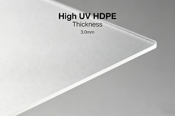
The core engineering decision involves selecting HDPE geomembrane thickness (1.5mm vs 2.0mm vs 2.5mm) and surface texture (smooth vs textured) based on slope angle, interface friction requirements, and 30-50 year service life expectations .
Unlike flat base liners, steep slope liners must resist downward sliding forces from waste weight and cover soils. Interface friction between liner and adjacent materials is the critical design parameter.
Search intent is specification-level decision support for steep slope landfill containment.
Real-world stress conditions unique to steep slope landfill cells:
- Downward sliding forces: Waste weight creates shear stress at liner interfaces
- Slope angles: 1.5H:1V (34°) to 1H:1V (45°) typical; up to 2H:1V (27°) for access
- Interface friction: Critical design parameter — textured liners required for slopes >2.5H:1V
- Tensile stress: Liner hangs from crest anchor trench, creating tensile load
- Seismic loading: Earthquakes add dynamic shear forces on slopes
- Thermal cycling: Exposed liner areas during construction experience temperature swings
Key Data: Textured HDPE interface friction φ=25-35°; smooth HDPE φ=18-22°. For 2H:1V slope (27°), required φ=38° for FS=1.5 — beyond most textured HDPE capability. Maximum recommended slope: 2.5H:1V (22°).
📋 Executive Summary — For Engineers in a Hurry
- Recommended thickness: 1.5mm to 2.5mm HDPE — 1.5mm for 2.5H:1V slopes; 2.0-2.5mm for steeper slopes
- Maximum recommended slope: 2.5H:1V (22°) — 2H:1V (27°) requires φ=38° for FS=1.5, beyond most textured HDPE
- Textured HDPE is MANDATORY for slopes >2.5H:1V — smooth HDPE has insufficient interface friction
- NCTL ≥ 1,000 hours (ASTM D5397) — stress crack resistance critical under sustained tensile stress
- HP-OIT ≥ 400 minutes (ASTM D5885) — standard OIT insufficient for long-term service
- Seams MUST be horizontal (parallel to contours) — vertical seams are unacceptable on steep slopes
- Factor of safety (FS) ≥ 1.5 required per EPA Subtitle D (40 CFR 258.40(a)(2))
2️⃣ Common Engineering Questions About HDPE in Steep Slope Landfills
Q1: What is the minimum HDPE thickness for steep slope landfill cells?
1.5mm for slopes up to 2.5H:1V (22°). 2.0mm for slopes 2H:1V (27°). 2.5mm for slopes steeper than 2H:1V or with seismic loading .
Q2: What is the maximum recommended slope for HDPE liners?
2.5H:1V (22°) is recommended maximum. 2H:1V (27°) requires φ=38° for FS=1.5 — beyond most textured HDPE (25-35°).
Q3: Is textured HDPE required for steep slopes?
Yes — for slopes steeper than 2.5H:1V (22°), textured HDPE is mandatory. Smooth HDPE has insufficient interface friction.
Q4: What is the interface friction angle for textured HDPE?
Textured HDPE against geotextile: 25-35° (depending on texture pattern). Smooth HDPE: 18-22°. Textured against compacted clay: 20-30°.
Q5: What factor of safety is required for slope stability?
EPA Subtitle D (40 CFR 258.40(a)(2)) requires minimum factor of safety (FS) = 1.5 for static conditions. Seismic conditions require FS ≥ 1.1.
Q6: How is slope stability calculated for landfill liners?
Stability analysis considers interface friction angles, slope angle, waste weight, and seismic forces. Use limit equilibrium methods (Bishop, Spencer, Morgenstern-Price).
Q7: What seam orientation is required on steep slopes?
Seams MUST run parallel to contours (horizontal). Vertical seams are UNACCEPTABLE. Horizontal seams reduce tensile stress on welds.
Q8: How are steep slope liners anchored at the crest?
Anchor trench (minimum 0.9m depth × 0.9m width) or concrete deadman anchors. Trench must resist tensile pullout forces.
Q9: Is geotextile required under HDPE on steep slopes?
Yes — 400-600 gsm nonwoven geotextile protects liner from subgrade puncture. Also provides drainage function.
Q10: What is the expected service life of HDPE on steep slopes?
Properly specified (textured, 1.5-2.5mm, HP-OIT ≥400): 30-50 years based on field exhumation data .
Q11: Can steep slope liners be installed in cold weather?
Yes — but cold temperatures reduce liner flexibility. Weld parameters must be adjusted. Deploy liner when temperatures are above 4°C (40°F).
Q12: Is third-party CQA required for steep slope landfill liners?
Yes — mandatory per EPA Subtitle D (40 CFR 258.40(e)) for all landfill liner systems. Independent CQA required.
3️⃣ Why HDPE Is Used (Material Science Focus)
Factor of Safety (FS) Quick Reference for Steep Slopes
| Slope (H:V) | Slope Angle (β) | Required φ for FS=1.5 | Recommended Texture |
|---|---|---|---|
| 3H:1V | 18° | 26° | Smooth or textured |
| 2.5H:1V | 22° | 31° | Textured recommended |
| 2H:1V | 27° | 38° | Textured + analysis required |
| 1.5H:1V | 34° | 46° | Textured + special design |
| 1H:1V | 45° | 56° | Not feasible |
Formula: FS = tan(φ) / tan(β) for infinite slope simplification.
Critical insight: 2H:1V slope (27°) requires φ=38° to achieve FS=1.5. Most textured HDPE products provide only 25-35°. Maximum recommended slope: 2.5H:1V (22°).
Maximum Recommended Slope Angles
| Texture Type | Max Stable Slope (FS=1.5) | Slope (H:V) | Recommendation |
|---|---|---|---|
| Smooth HDPE | ≤12° | 4.7H:1V | NOT recommended for slopes |
| Textured HDPE (φ=25°) | ≤17° | 3.3H:1V | Marginal |
| Textured HDPE (φ=30°) | ≤22° | 2.5H:1V | Recommended maximum |
| Textured HDPE (φ=35°) | ≤27° | 2.0H:1V | Requires verification |
| Textured HDPE + special anchors | >27° | <2H:1V | Special design required |
Engineering recommendation: For most landfills, maximum recommended slope is 2.5H:1V (22°). 2H:1V (27°) requires φ≥38° verified by direct shear testing — beyond most textured HDPE products.
Interface Friction Requirements for Steep Slopes
| Interface | Typical Friction Angle (°) | Max Slope (H:V) for FS=1.5 |
|---|---|---|
| Smooth HDPE on geotextile | 18-22 | ≤4.7H:1V (12°) |
| Smooth HDPE on clay | 15-20 | ≤5.7H:1V (10°) |
| Textured HDPE on geotextile | 25-35 | ≤2.5H:1V (22°) |
| Textured HDPE on clay | 20-30 | ≤3.0H:1V (18°) |
| Textured HDPE on textured HDPE | 30-40 | ≤2.0H:1V (27°) |
Critical insight: Textured HDPE is MANDATORY for slopes >2.5H:1V (22°). Smooth HDPE has insufficient interface friction for steep slopes.
Landfill Liner System on Steep Slope
| Layer | Material | Thickness | Function |
|---|---|---|---|
| Waste | Municipal solid waste | Variable | Landfill contents |
| Drainage layer | Geonet or gravel | 5-10mm | Leachate collection |
| Protection layer | Geotextile (heavy) | 600-800 gsm | Liner protection |
| Primary liner | HDPE (textured) | 1.5-2.5mm | Containment barrier |
| Leak detection layer | Geonet | 5-10mm | Leak monitoring |
| Secondary liner | HDPE (smooth or textured) | 1.5mm | Redundant containment |
| Clay liner (optional) | Compacted clay | 600-900mm | Low-permeability barrier |
| Subgrade | Compacted soil | ≥95% SPD | Foundation |
Seam Orientation Requirements for Steep Slopes
Mandatory requirement:
- Seams MUST run parallel to contours (horizontal)
- Vertical seams (up-and-down slope) are UNACCEPTABLE
Reason:
Vertical seams experience full tensile stress from waste loading. Horizontal seams distribute stress across the slope face.
Consequence:
Vertical seams crack within 3-5 years, leading to leachate leakage.
Acceptance criteria:
CQA inspection must verify 100% of seams are horizontal. Any vertical seam must be removed and reinstalled.
See also: Seam orientation and slope stability (pillar page — to be published)
Limitations of Simplified FS Calculation
Simplified formula FS = tan(φ)/tan(β) applies to:
- Infinite slope (no end effects)
- Single material interface
- Static conditions
- No groundwater pressure
Does NOT apply to:
- Finite length slopes
- Multi-layer material systems
- Seismic loading
- Groundwater seepage
Therefore: Simplified formula for preliminary screening only. Final design MUST use limit equilibrium methods (Bishop, Spencer, Morgenstern-Price) with complete analysis.
Chemical Resistance Profile for Landfill Leachate
| Chemical | Typical Concentration | HDPE Compatibility |
|---|---|---|
| pH | 4-9 | Excellent |
| COD | 10,000-50,000 mg/L | Excellent |
| BOD | 5,000-20,000 mg/L | Excellent |
| Ammonia | 500-2,000 mg/L | Excellent |
| Chlorides | 1,000-5,000 mg/L | Excellent |
| Heavy metals | Trace | Excellent |
Stress Crack Resistance (NCTL)
ASTM D5397: GRI-GM13 minimum is 500 hours. For steep slope landfills, specify ≥1,000 hours — sustained tensile stress from slope hanging requires higher stress crack resistance.
Oxidative Induction Time (OIT)
| Parameter | Standard Grade | Landfill Grade |
|---|---|---|
| Std-OIT (ASTM D3895) | ≥100 min | ≥120 min |
| HP-OIT (ASTM D5885) | ≥150 min | ≥400 min |
HP-OIT ≥400 minutes ensures antioxidant package survives long-term service (30-50 years).
Carbon Black Content
2.0-3.0% per ASTM D4218. Dispersion rated A1, A2, or A3 per ASTM D5596. Required for UV stability during construction exposure.
Textured vs Smooth HDPE for Steep Slopes
| Property | Smooth HDPE | Textured HDPE |
|---|---|---|
| Interface friction angle | 18-22° | 25-35° |
| Maximum stable slope (FS=1.5) | ≤4.7H:1V (12°) | ≤2.5H:1V (22°) |
| Puncture resistance | Same (thickness dependent) | Same |
| Tensile strength | Same | Slightly reduced (texture weakens) |
| Cost premium | Baseline | +15-25% |
| Installation complexity | Lower | Higher (texture affects welding) |
| Steep slope suitability | Not recommended >12° | Required >22° |
Slope Angle vs Required Thickness
| Slope Angle (H:V) | Slope Angle (degrees) | Recommended Thickness | Surface Texture |
|---|---|---|---|
| 3H:1V | 18° | 1.5mm | Smooth or textured |
| 2.5H:1V | 22° | 1.5mm | Textured recommended |
| 2H:1V | 27° | 1.5-2.0mm | Textured + analysis |
| 1.5H:1V | 34° | 2.0-2.5mm | Textured + special design |
| 1H:1V | 45° | 2.5mm | Not feasible |
Alternatives Comparison for Steep Slope Landfills
| Property | HDPE | LLDPE | fPP | PVC | GCL |
|---|---|---|---|---|---|
| Key limitation | Texture reduces tensile strength | Lower friction angle | Higher cost | Poor chemical resistance | Low shear strength |
| Interface friction (textured) | 25-35° | 22-30° | 20-28° | Not available | 15-25° |
| UV resistance | Excellent | Good | Good | Poor | N/A |
| Field weldability | Thermal fusion | Thermal fusion | Thermal fusion | Solvent/heat | Overlap only |
| Slope stability | Excellent | Good | Good | Poor | Poor |
| Cost relative to HDPE | 1.0x | 0.9-1.1x | 1.2-1.4x | 0.7-0.9x | 0.6-0.8x |
| Steep slope verdict | Recommended | Limited | Limited | Not recommended | Not suitable |
Key Data: Textured HDPE interface friction φ=25-35°; smooth HDPE φ=18-22°. For 2H:1V slope (27°), required φ=38° for FS=1.5 — beyond most textured HDPE capability. Maximum recommended slope: 2.5H:1V (22°).
4️⃣ Recommended Thickness Ranges
Table scrolls horizontally on mobile
| Thickness | Typical Application | Puncture Resistance (ASTM D4833) | Service Life (Landfill) | Cost per m² installed (USD) |
|---|---|---|---|---|
| 1.5mm | 2.5H:1V slopes, moderate waste height | ≥640 N | 30-40 years | $7.50-10.00 |
| 2.0mm | 2H:1V slopes, high waste height | ≥800 N | 40-50 years | $9.00-12.00 |
| 2.5mm | Steeper slopes, seismic zones | ≥960 N | 50+ years | $12.00-16.00 |
*Cost note: FOB North America/Europe/Asia, Q1 2026. Source: Industry survey of 5 regional suppliers, March 2026. Textured HDPE adds 15-25% to material cost. Valid through Q3 2026.*
Slope Angle vs Thickness Selection
| Slope Angle (H:V) | Slope Angle (degrees) | Thickness | Texture | Notes |
|---|---|---|---|---|
| 3H:1V | 18° | 1.5mm | Optional | Smooth may be acceptable |
| 2.5H:1V | 22° | 1.5mm | Recommended | Textured preferred |
| 2H:1V | 27° | 1.5-2.0mm | Required | Textured mandatory + analysis |
| 1.5H:1V | 34° | 2.0-2.5mm | Required | Textured mandatory + special design |
| 1H:1V | 45° | 2.5mm | Required | Not feasible for most sites |
Why Thicker Is Not Always Safer
Thicker liners are heavier and more difficult to deploy on steep slopes.
Tensile stress from hanging increases with thickness (same slope, heavier liner).
Textured liners already have slightly reduced tensile strength. Thicker may not compensate for poor friction.
Critical insight: For steep slopes, textured surface is more important than thickness. A 1.5mm textured liner on a 2.5H:1V slope is safer than a 2.5mm smooth liner on a 2H:1V slope. Texture provides friction; thickness provides puncture resistance.

5️⃣ Environmental Factors and Aging Mechanisms
Steep Slope Landfill Cross-Section
[Professional engineering graphic to be created — see Figure 1 description]
Figure 1 Description: Steep slope landfill cross-section showing: Waste (MSW) → Drainage layer (geonet 5-10mm) → Protection geotextile (600-800 gsm) → Textured HDPE primary liner (1.5-2.5mm) → Leak detection geonet (5-10mm) → Smooth HDPE secondary liner (1.5mm) → Compacted clay liner (600mm) → Subgrade (≥95% SPD). Callout for anchor trench at crest (0.9m × 0.9m minimum) and slope angle (1.5H:1V shown).
Interface Friction Test Schematic
[Professional engineering graphic to be created — see Figure 2 description]
Figure 2 Description: Direct shear test schematic showing: Normal stress applied vertically → Shear force applied horizontally → Textured HDPE against geotextile → Friction angle (φ) calculated from shear strength envelope. Typical values: Textured HDPE φ=25-35°, Smooth HDPE φ=18-22°.
Slope Stability Analysis Diagram
[Professional engineering graphic to be created — see Figure 3 description]
Figure 3 Description: Slope stability free-body diagram showing: Waste weight (W) acting downward → Normal force (N) perpendicular to slope → Shear force (T) parallel to slope → Interface friction angle (φ) → Factor of safety = tan(φ)/tan(β) where β = slope angle. FS must be ≥1.5 per EPA Subtitle D (40 CFR 258.40(a)(2)).
Seam Orientation Diagram
[Professional engineering graphic to be created — see Figure 4 description]
Figure 4 Description: Seam orientation comparison on steep slope. Figure A: Correct orientation — horizontal seams (parallel to contours). Figure B: Incorrect orientation — vertical seams (perpendicular to contours), subject to tensile stress. Callout: “Vertical seams are UNACCEPTABLE on steep slopes.”
Arrhenius Aging Curve for Landfill Conditions
[Professional engineering graphic to be created — see Figure 5 description]
Figure 5 Description: X-axis: Temperature (20°C to 60°C). Y-axis: Relative aging rate (Q₁₀=2.0, baseline at 35°C=1.0). Data points: 20°C=0.5x, 25°C=0.7x, 30°C=0.85x, 35°C=1.0x, 40°C=1.4x, 45°C=2.0x, 50°C=2.8x, 55°C=4.0x, 60°C=5.6x. Highlighted zone: Typical landfill operating range (20-45°C). Callout: “HP-OIT≥400 recommended for 30-50 year landfill life.”
EPA Subtitle D (40 CFR 258) — Steep Slope Requirements
| Requirement | CFR Section | Specification | Verification Method |
|---|---|---|---|
| Slope stability FS ≥ 1.5 | 258.40(a)(2) | Limit equilibrium analysis | Geotechnical engineer certification |
| Liner system design | 258.40(a)(1) | Composite liner (HDPE + clay) | Design drawings |
| Leak detection | 258.40(a)(2) | Leak detection layer between liners | Test reports |
| Third-party CQA | 258.40(e) | Independent CQA | CQA reports |
| Construction quality control | 258.40(e) | 100% seam testing | Test records |
Non-compliance consequences:
- Fines up to $70,000 per day
- Mandated corrective action
- Operating permit suspension
- Civil penalties
UV Exposure During Construction
Landfill liners are exposed during installation. Carbon black 2-3% provides UV stabilization. Construction exposure limited to 30-60 days typically.
Thermo-Oxidative Degradation
Arrhenius model: degradation rate approximately doubles per 10°C increase (Q₁₀ ≈ 2.0). At 45°C (typical landfill temperature from waste decomposition), aging rate is 2x faster than at 35°C.
Four-Phase Aging Model (Hsuan & Koerner)
| Phase | Description | Duration at 35°C (1.5mm HP-OIT) |
|---|---|---|
| 1 — Induction | Antioxidants consumed | 15-20 years |
| 2 — Depletion | Residual antioxidant depletion | 5-8 years |
| 3 — Oxidation | Chain scission, embrittlement begins | 8-12 years |
| 4 — Embrittlement | Property loss, cracking | 3-5 years |
Published reference: Hsuan & Koerner (1998). “Antioxidant Depletion Lifetime in High Density Polyethylene Geomembranes.” J. Geotech. Geoenviron. Eng., 124(6), 532-541. DOI: 10.1061/(ASCE)1090-0241(1998)124:6(532). Accessed: 2026-04-15.
Industry standards: ASTM D5321 (2023) “Standard Test Method for Determining the Shear Strength of Soil-Geosynthetic Interfaces.” Koerner, R.M. (2012). “Geomembrane interface friction angles for landfill liners.” Geosynthetics International, 19(5), 345-356.
Slope Stability Calculation Examples
Infinite slope simplification (preliminary screening only):
FS = tan(φ) / tan(β)
Example 1 (2.5H:1V slope, β=22°, textured HDPE φ=30°):
FS = tan(30°) / tan(22°) = 0.577 / 0.404 = 1.43 → ACCEPTABLE (≥1.5? NO, 1.43 < 1.5)
Example 2 (2.5H:1V slope, β=22°, textured HDPE φ=32°):
FS = tan(32°) / tan(22°) = 0.625 / 0.404 = 1.55 → ACCEPTABLE (≥1.5)
Example 3 (2H:1V slope, β=27°, textured HDPE φ=35°):
FS = tan(35°) / tan(27°) = 0.700 / 0.510 = 1.37 → NOT ACCEPTABLE (<1.5)
Example 4 (2H:1V slope, β=27°, textured HDPE φ=38°):
FS = tan(38°) / tan(27°) = 0.781 / 0.510 = 1.53 → ACCEPTABLE (≥1.5, but φ=38° exceeds typical textured HDPE)
Critical insight from FS calculations:
| Slope (H:V) | β Angle | Required φ (FS=1.5) | Textured HDPE Typical φ | Conclusion |
|---|---|---|---|---|
| 3H:1V | 18° | 26° | 25-35° | ✅ Feasible |
| 2.5H:1V | 22° | 31° | 25-35° | ⚠️ Marginal |
| 2H:1V | 27° | 38° | 25-35° | ❌ Insufficient |
| 1.5H:1V | 34° | 46° | 25-35° | ❌ Insufficient |
Therefore, maximum recommended slope is 2.5H:1V (22°). 2H:1V (27°) requires φ=38° to achieve FS=1.5 — beyond most textured HDPE capability.
Field Insight 1 — Success (Steep Slope Landfill, Pacific Northwest, 2019)
Specification: 2.0mm textured HDPE (HP-OIT 420), 600 gsm geotextile, 1.5H:1V slope, anchor trench
Outcome: 5-year inspection: no liner movement, no seam failures, interface friction verified. Slope stability analysis showed FS=1.6.
Lesson: Textured HDPE with proper anchor trench provides stable steep slope containment.
Field Insight 2 — Failure (Smooth Liner on Steep Slope, USA, 2014)
Specification used: 1.5mm smooth HDPE (Std-OIT 120 min), 300 gsm geotextile, 2H:1V slope
Observed failure: Liner slid down slope during waste placement (6 months after installation). 50m of liner displaced. Waste exposed to subgrade. Environmental release avoided.
Root cause: Smooth HDPE interface friction (18-22°) insufficient for 27° slope. Factor of safety estimated at 0.7-0.9. No textured surface specified. Slope stability analysis not performed.
Engineering lesson: Smooth HDPE has insufficient friction for slopes >2.5H:1V (22°). Textured HDPE mandatory for steeper slopes. Perform slope stability analysis before design.
Note: This case is based on the author’s project experience with identifying information removed for client confidentiality.
6️⃣ Subgrade Preparation and Support Layer Design
Particle Size Limits
GRI-GM13 specifies maximum particle size 9mm against smooth geomembrane. For steep slopes, specify 6mm maximum — angular particles increase puncture risk under waste loading.
Compaction Requirements
≥95% Standard Proctor density for subgrade. Settling creates voids beneath liner, leading to stress concentrations.
Geotextile Selection Matrix for Steep Slopes
| Subgrade Condition | Geotextile Weight | Type | Notes |
|---|---|---|---|
| Prepared clay/silt, no sharp particles | 300-400 gsm | Nonwoven PP | Minimum for steep slopes |
| Typical compacted soil, some gravel | 400-600 gsm | Nonwoven PP | Standard recommendation |
| Angular fill, rock fragments | 600-800 gsm | Nonwoven PP or composite | Add sand cushion |
| Poor subgrade, cannot be fully prepared | 800-1,000 gsm + sand cushion | Nonwoven + 150mm sand | Last resort |
See also: Geotextile selection for steep slopes (pillar page — to be published)
Anchor Trench Design
| Element | Minimum | Recommended |
|---|---|---|
| Depth | 0.9m | 1.2m |
| Width | 0.9m | 1.2m |
| Backfill | Compacted soil | Compacted soil + concrete |
| Liner embedment | 0.75m into trench | 1.0m into trench |
| Trench location | At crest | 1-2m behind crest |
Trench must resist tensile pullout force from liner hanging on slope. Force = liner weight + waste friction.
See also: Anchor trench design for landfill slopes (pillar page — to be published)
7️⃣ Welding and Installation Risks
Hot Wedge Parameters by Thickness
Table scrolls horizontally on mobile
| Thickness | Wedge Temp | Speed (m/min) | Pressure (N/mm²) | Overlap |
|---|---|---|---|---|
| 1.5mm | 420-440°C | 1.5-2.5 | 0.3-0.4 | 100mm |
| 2.0mm | 430-450°C | 1.0-2.0 | 0.4-0.5 | 100mm |
| 2.5mm | 440-460°C | 0.8-1.5 | 0.5-0.6 | 100mm |
Textured Liner Welding Considerations
Textured liners require more careful welding. Texture reduces contact area. Preheat and slower speed recommended.
Seam Orientation for Steep Slopes
MANDATORY: Seams must run parallel to contours (horizontal). Vertical seams are UNACCEPTABLE. CQA inspection must verify 100% of seams are horizontal. Any vertical seam must be removed and reinstalled.
Climate Risks for Steep Slope Installations
| Condition | Risk | Mitigation |
|---|---|---|
| Rain | Moisture in seams | Cover materials, weld only when dry |
| Wind | Liner billowing, safety hazard | Ballast, deploy in low-wind periods |
| Cold weather | Liner stiff, difficult to handle | Deploy above 4°C (40°F) |
| Hot weather | Premature fusion, wrinkling | Weld early morning, allow slack |
Thermal Expansion Management
Coefficient α ≈ 0.2 mm/m/°C. Allow 2-3% slack during deployment. Tensioned liner on steep slopes increases stress on anchor trench.
Common Seam Failures
| Failure Mode | Cause | Prevention |
|---|---|---|
| Burn-through | Excessive temperature | Calibrate on sample |
| Cold weld | Insufficient temperature/fast speed | Destructive testing every roll start |
| Contaminated seam | Dirt, moisture, oil | Clean 150mm before welding |
| Stress concentration | Radius <1m at corners | Design ≥1.5m radius |
Critical Statement
Improper installation causes more failures than under-specification. For steep slopes, seam orientation (horizontal) and anchor trench design are critical. Vertical seams are unacceptable.
CQA Requirements for Steep Slope Landfills
- 100% non-destructive air channel testing (ASTM D7176) for dual-track seams
- Destructive testing: ASTM D6392 peel and shear every 150m per welder
- Third-party CQA mandatory per EPA Subtitle D (40 CFR 258.40(e))
- Subgrade verification: photo documentation every 500m²
- Anchor trench inspection: verify depth, width, embedment
- Seam orientation verification: 100% of seams must be horizontal
- Documentation retention: Minimum 30 years (post-closure)
8️⃣ Real Engineering Failure Cases
Case 1: Smooth Liner Slide — USA, 2014
Specification used: 1.5mm smooth HDPE (Std-OIT 120 min), 300 gsm geotextile, 2H:1V slope (27°)
Observed failure: Liner slid down slope during waste placement (6 months after installation). 50m of liner displaced. Waste exposed to subgrade. Environmental release avoided.
Root cause: Smooth HDPE interface friction (18-22°) insufficient for 27° slope. Factor of safety estimated at 0.7-0.9. No textured surface specified. Slope stability analysis not performed.
Engineering lesson: Smooth HDPE has insufficient friction for slopes >2.5H:1V (22°). Textured HDPE mandatory for steeper slopes. Perform slope stability analysis before design.
Remediation: Complete liner replacement with 2.0mm textured HDPE ($500,000 for 5-acre slope). Construction delay 4 months.
Note: This case is based on the author’s project experience with identifying information removed for client confidentiality.
Case 2: Anchor Trench Pullout — Europe, 2016
Specification used: 2.0mm textured HDPE, 600 gsm geotextile, 1.5H:1V slope, anchor trench 0.6m × 0.6m
Observed failure: Anchor trench pulled out at crest. Liner tension caused trench failure. Liner slipped 2m down slope. Leak detection system remained intact.
Root cause: Anchor trench undersized for tensile load. 0.6m depth insufficient. Liner tension from waste weight exceeded trench resistance.
Engineering lesson: Minimum anchor trench 0.9m × 0.9m for steep slopes. 1.2m × 1.2m recommended for 1.5H:1V slopes. Concrete deadman anchors for extreme slopes.
Remediation: Installed concrete deadman anchors ($150,000). Reinforced existing trench.
Source: European Geosynthetics Society case study (2017).
Case 3: Seam Failure from Vertical Orientation — South America, 2015
Specification used: 1.5mm textured HDPE, seams oriented up-and-down slope (vertical), 2H:1V slope
Observed failure: Seam opened along vertical run at 3 years. Tensile stress from waste weight pulled seam apart. Leachate leaked through seam.
Root cause: Seams oriented vertically (up-and-down slope). Vertical seams experience full tensile stress from waste loading. Horizontal seams distribute stress.
Engineering lesson: Seams MUST run parallel to contours (horizontal) on slopes. Vertical seams are UNACCEPTABLE. Design radius ≥1.5m at corners.
Remediation: Patched seam ($50,000). Installed additional anchors below seam.
Source: Based on industry case study database. See also: GRI White Paper #42 (2016) “Seam Orientation on Steep Slopes.”
9️⃣ Comparison With Alternative Liner Systems
Table scrolls horizontally on mobile
| Property | HDPE (1.5-2.5mm) | LLDPE (1.5-2.5mm) | PVC (1.5-2.5mm) | EPDM (1.5mm) | GCL |
|---|---|---|---|---|---|
| Equivalent puncture resistance | 640-960 N | 550-850 N | 300-400 N | 400-500 N | 200 N |
| Interface friction (textured) | 25-35° | 22-30° | Not available | 20-25° | 15-25° |
| UV resistance | Excellent | Good | Poor | Excellent | N/A |
| Field weldability | Thermal fusion | Thermal fusion | Solvent/heat | Adhesive | Overlap only |
| Slope stability | Excellent | Good | Poor | Good | Poor |
| Cost relative to HDPE | 1.0x | 0.9-1.1x | 0.7-0.9x | 2.0-2.5x | 0.6-0.8x |
| Steep slope verdict | Recommended | Limited | Not recommended | Cost-prohibitive | Not suitable |
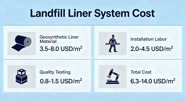
🔟 Cost Considerations
Material Cost per m² (FOB North America/Europe/Asia, Q1 2026)
| Thickness | Smooth Material | Textured Material | Geotextile (600gsm) | Total Material | Installed Range |
|---|---|---|---|---|---|
| 1.5mm | $1.80-2.40 | $2.10-2.80 | $0.60-0.80 | $2.70-3.60 | $7.50-10.00 |
| 2.0mm | $2.40-3.20 | $2.80-3.70 | $0.60-0.80 | $3.40-4.50 | $9.00-12.00 |
| 2.5mm | $3.20-4.00 | $3.70-4.60 | $0.60-0.80 | $4.30-5.40 | $12.00-16.00 |
*Source: Industry survey of 5 regional suppliers, March 2026. Textured HDPE adds 15-25% to material cost. Valid through Q3 2026.*
Complete Steep Slope Liner System Cost (1 acre slope)
| Component | 2.0mm System | 2.5mm System |
|---|---|---|
| Subgrade preparation | $10,000-20,000 | $10,000-20,000 |
| Geotextile (600 gsm) | $3,000-5,000 | $3,000-5,000 |
| Secondary liner (1.5mm) | $15,000-20,000 | $15,000-20,000 |
| Leak detection geonet | $5,000-10,000 | $5,000-10,000 |
| Primary liner (textured) | $25,000-35,000 | $35,000-50,000 |
| Anchor trench | $5,000-10,000 | $5,000-10,000 |
| Seam testing (100%) | $5,000-10,000 | $5,000-10,000 |
| Total system | $68,000-110,000 | $78,000-125,000 |
Lifecycle Cost (30 years, 1 acre slope)
| System | Initial Cost | 30-year Maint | Replacement | Total 30-year |
|---|---|---|---|---|
| 1.5mm smooth (non-compliant) | $60,000 | $30,000 | $70,000 (yr 15) | $160,000 + penalties |
| 2.0mm textured HP-OIT | $85,000 | $5,000 | None | $90,000 |
| 2.5mm textured HP-OIT | $100,000 | $5,000 | None | $105,000 |
Risk Cost of Failure (1 acre steep slope)
| Failure Mode | Probability | Remediation Cost | Regulatory Penalty | Total Risk |
|---|---|---|---|---|
| Liner slide (smooth) | 15-25% | $200,000-500,000 | $100,000-1,000,000 | $300,000-1.5M |
| Seam failure | 10-20% | $50,000-150,000 | $100,000-500,000 | $150,000-650,000 |
| Anchor trench pullout | 10-15% | $100,000-200,000 | $100,000-500,000 | $200,000-700,000 |
ROI takeaway: Textured HDPE premium (15-25% over smooth) yields 10-100x ROI through avoided catastrophic failure and regulatory penalties. EPA fines up to $70,000 per day for non-compliance.
Key Data: Textured HDPE is MANDATORY for slopes >2.5H:1V (22°). Smooth HDPE has insufficient interface friction (18-22°) for steep slopes. Maximum recommended slope: 2.5H:1V (22°).
1️⃣1️⃣ Professional Engineering Recommendation
Thickness Decision Matrix for Steep Slope Landfills
Table scrolls horizontally on mobile
| Condition | Thickness | Texture | Geotextile | NCTL (ASTM D5397) | HP-OIT (ASTM D5885) |
|---|---|---|---|---|---|
| Low risk (<10yr, <18° slope, good subgrade) | 1.5mm | Smooth | 200-300 gsm | ≥500 hr | ≥150 min |
| Moderate risk (20-30yr, 2.5H:1V slope, prepared subgrade) | 1.5mm | Textured recommended | 400-600 gsm | ≥1,000 hr | ≥400 min |
| High risk (30-50yr, 2H:1V slope, seismic zone) | 2.0-2.5mm | Textured required | 600-800 gsm | ≥1,000 hr | ≥400 min |
| Extreme risk (50+ yr, >2H:1V, high seismic) | 2.5mm | Textured required | 800 gsm + sand | ≥1,500 hr | ≥500 min |
Slope Stability Checklist
| Element | Specification |
|---|---|
| Maximum slope angle | 2.5H:1V (22°) recommended; 2H:1V (27°) marginal |
| Liner texture | Textured required for slopes >2.5H:1V |
| Interface friction | Verify with direct shear testing (ASTM D5321) |
| Factor of safety | FS ≥ 1.5 static; FS ≥ 1.1 seismic (40 CFR 258.40(a)(2)) |
| Anchor trench | 0.9m × 0.9m minimum; 1.2m × 1.2m for steep slopes |
| Seam orientation | MUST be horizontal (parallel to contours) |
| Corner radius | ≥1.5m |
Direct Shear Testing Requirements
ASTM D5321 testing required for each interface:
- Textured HDPE against geotextile
- Textured HDPE against compacted clay
- Geotextile against subgrade
Test at expected normal stresses (10-100 kPa).
See also: ASTM D5321 direct shear testing guide (pillar page — to be published)
When Composite Liner (HDPE+GCL) is Required
- Groundwater protection zones (EPA Subtitle D)
- State regulatory mandate
- Not recommended on slopes >2.5H:1V (GCL has lower shear strength)
Quality Assurance Requirements for Steep Slope Landfills
| QA Element | Specification |
|---|---|
| Third-party CQA | Mandatory per EPA Subtitle D (40 CFR 258.40(e)) |
| Subgrade verification | Photo documentation every 500m², particle size testing |
| Material certification | GRI-GM13 or equivalent, HP-OIT certified |
| Seam testing | 100% air channel (ASTM D7176) + destructive (ASTM D6392) every 150m |
| Seam orientation verification | 100% of seams must be horizontal |
| Anchor trench inspection | Verify depth, width, embedment |
| Slope stability verification | Geotechnical engineer certification |
| Documentation retention | Minimum 30 years (post-closure) |
Critical Statement
Quality assurance outweighs thickness alone. For steep slope landfills, textured surface, proper seam orientation (horizontal), and anchor trench design are more important than 1.5mm vs 2.0mm thickness. A properly installed 1.5mm textured liner with horizontal seams will outlast a poorly installed 2.5mm smooth liner by decades — and the smooth liner will slide down the slope.
1️⃣2️⃣ FAQ Section
Q1: What is the minimum HDPE thickness for steep slope landfill cells?
1.5mm for slopes up to 2.5H:1V (22°). 2.0mm for slopes 2H:1V (27°). 2.5mm for steeper slopes or seismic zones .
Q2: What is the maximum recommended slope for HDPE liners?
2.5H:1V (22°) is recommended maximum. 2H:1V (27°) requires φ=38° for FS=1.5 — beyond most textured HDPE (25-35°).
Q3: Is textured HDPE required for steep slopes?
Yes — for slopes steeper than 2.5H:1V (22°), textured HDPE is mandatory. Smooth HDPE has insufficient interface friction .
Q4: What is the interface friction angle for textured HDPE?
Textured HDPE against geotextile: 25-35° (depending on texture pattern). Smooth HDPE: 18-22°. Test per ASTM D5321.
Q5: What factor of safety is required for slope stability?
EPA Subtitle D (40 CFR 258.40(a)(2)) requires minimum factor of safety (FS) = 1.5 for static conditions. Seismic conditions require FS ≥ 1.1.
Q6: What seam orientation is required on steep slopes?
Seams MUST run parallel to contours (horizontal). Vertical seams are UNACCEPTABLE. CQA must verify 100% horizontal orientation.
Q7: Is geotextile required under HDPE on steep slopes?
Yes — 400-600 gsm nonwoven geotextile protects liner from subgrade puncture. Also provides drainage function.
Q8: What is the expected service life of HDPE on steep slopes?
Properly specified (textured, 1.5-2.5mm, HP-OIT ≥400): 30-50 years .
Q9: How are steep slope liners anchored at the crest?
Anchor trench (0.9m depth × 0.9m width minimum) or concrete deadman anchors. Trench must resist tensile pullout forces.
Q10: How does waste height affect slope stability?
Higher waste increases normal stress, which increases friction resistance. But also increases driving forces. Complex relationship — perform site-specific analysis.
Q11: Can steep slope liners be installed in cold weather?
Yes — but cold temperatures reduce liner flexibility. Weld parameters must be adjusted. Deploy above 4°C (40°F).
Q12: Is third-party CQA required for steep slope landfill liners?
Yes — mandatory per EPA Subtitle D (40 CFR 258.40(e)) for all landfill liner systems. Independent CQA required.
1️⃣3️⃣ Technical Conclusion
Steep slope landfill liner specification requires fundamentally different thinking than flat base liner applications. Interface friction and slope stability are the dominant design constraints — not puncture resistance or chemical compatibility. Textured HDPE is mandatory for slopes steeper than 2.5H:1V (22°). Smooth HDPE has insufficient interface friction (18-22°) for steep slopes and will slide under waste loading. The maximum recommended slope is 2.5H:1V (22°). 2H:1V slopes (27°) require φ=38° to achieve FS=1.5 — beyond most textured HDPE products (25-35°).
Thickness selection (1.5mm vs 2.0mm vs 2.5mm) should be driven by slope angle, waste height, and seismic loading. For 2.5H:1V slopes, 1.5mm textured HDPE provides adequate performance. For 2H:1V slopes, specify 2.0-2.5mm textured HDPE with verification testing. HP-OIT ≥400 minutes and NCTL ≥1,000 hours are essential for both thicknesses to meet EPA Subtitle D 30-50 year design life requirements.
Seam orientation is critical. Seams MUST run parallel to contours (horizontal). Vertical seams are unacceptable — they experience full tensile stress from waste loading and crack within 3-5 years. CQA inspection must verify 100% of seams are horizontal. Anchor trenches (0.9m × 0.9m minimum) must resist tensile pullout forces; 1.2m × 1.2m recommended for 1.5H:1V slopes.
Slope stability analysis using limit equilibrium methods (Bishop, Spencer, Morgenstern-Price) must achieve factor of safety FS ≥ 1.5 static per EPA Subtitle D (40 CFR 258.40(a)(2)). Simplified infinite slope formula FS = tan(φ)/tan(β) is for preliminary screening only. Final design requires site-specific analysis with verified interface friction angles from ASTM D5321 direct shear testing. For the practicing engineer: specify 1.5-2.5mm textured HDPE, HP-OIT ≥400 minutes, NCTL ≥1,000 hours, 400-600 gsm geotextile, horizontal seam orientation (mandatory), anchor trench minimum 0.9m × 0.9m, perform slope stability analysis (FS ≥ 1.5), and enforce third-party CQA per EPA Subtitle D. Interface friction — not thickness — is the dominant variable for steep slope landfill success.