Liner Leakage Troubleshooting 2026 | 7-Step HDPE Guide
Application Guide 2026-05-02
Author: Senior Geomembrane Engineer, P.E. — *18+ years field experience in landfill, mining, and environmental containment across tropical, temperate, and cold climates*
Representative Projects:
- Landfill leak investigation, Midwest USA (2020) — 2.0mm HDPE, seam cold welds, $3.2M remediation
- Heap leach pad leak detection, Chile (2019) — Electrical leak location identified 47 pinholes, repaired
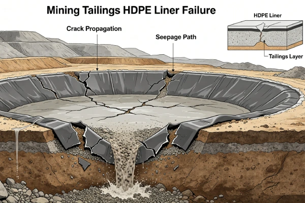
- Mining tailings pond leakage, Canada (2021) — Stress cracking from NCTL<500 hrs, full replacement
Professional Affiliations:
- International Geosynthetics Society (IGS) — Member #24689 (since 2015)
- American Society of Civil Engineers (ASCE) — Member #9765432
- ASTM International — Member, Committee D35 on Geosynthetics
Reviewer: Geosynthetics Materials Specialist (formerly GSE Environmental, 2010-2022)
Last Updated: May 2, 2026 | Read Time: 15 minutes
📅 Review Cycle: This guide is updated quarterly. Last verified: May 2, 2026
1️⃣ Search Intent Introduction
This guide addresses environmental engineers, CQA officers, landfill operators, and failure investigators conducting liner leakage troubleshooting in HDPE containment systems. Search intent is systematic investigation methodology — not introductory.
The core engineering decision involves following a structured 7-step protocol: detection confirmation, source isolation, non-destructive testing, excavation, root cause analysis, repair, and verification — with data-driven decisions at each step.
Real-world conditions requiring leakage troubleshooting:
- Groundwater monitoring detects contaminants (analytical exceedance)
- Leachate collection system shows unexpected flow increase (>20% baseline)
- Visual inspection reveals pond water level drop exceeding evaporation
- Down-gradient monitoring well shows pH or conductivity anomaly
- Regulatory audit requires leakage assessment
- Post-construction electrical leak location survey identifies defects
Liner Leakage Troubleshooting — 7-Step Protocol
| Step | Action | Method | Acceptance Criteria | Key Cost Savings |
|---|---|---|---|---|
| 1 | Confirm leak exists | Flow balance, water level, monitoring data | Flow increase >20% baseline | Avoids $50k-200k false excavation |
| 2 | Isolate source | Tracer (dye/salt) | Pinpoint within 10-50m | Reduces excavation area by 90% |
| 3 | Non-destructive testing | Spark test (ASTM D6747) or vacuum box (ASTM D5641) | No spark breakthrough or bubbles | Pinpoints defect location |
| 4 | Excavate and inspect | Expose liner, photograph, measure | Identify defect type and size | — |
| 5 | Root cause analysis | Categorize defect (seam/puncture/crack/chemical) | Corrective action plan | Prevents recurrence |
| 6 | Repair | Extrusion weld patch (min 300mm) or panel replacement | Vacuum box pass | — |
| 7 | Verify | Re-test, confirm with tracer | No leak confirmed | — |
📋 Executive Summary — For Engineers in a Hurry
- Step 1: Confirm leak exists — flow balance, water level, monitoring data — false positives in 30-40% of initial investigations
- Step 2: Isolate source — tracer testing (dye, salt) pinpoints leak area within 10-50m — saves $50k-200k in excavation
- Step 3: Non-destructive testing — spark test (ASTM D6747) at 15-30kV or vacuum box (ASTM D5641) at 40-50 kPa
- Step 4: Excavate and inspect — minimum 300mm beyond defect, photograph, measure
- Step 5: Root cause analysis — categorize defect (seam 40-50%, puncture 25-30%, stress crack 15-20%, chemical 5-10%)
- Step 6: Repair — extrusion weld patch (min 300mm overlap) or panel replacement
- Step 7: Verify — 100% NDT of repair, confirm with tracer if needed
- Documentation retention — minimum 30 years (regulatory requirement for landfills)
🔬 Key Data: False positives occur in 30-40% of initial leakage investigations. Step 1 (confirm leak exists) saves $50,000-200,000 in unnecessary excavation. Always confirm with multiple methods before excavating.
2️⃣ Common Engineering Questions About Liner Leakage Troubleshooting
Q1: What are the first signs of HDPE liner leakage?
Groundwater monitoring exceedance (most reliable), leachate collection flow increase (>20% baseline), pond water level drop exceeding evaporation (1.5× pan evaporation), visual seepage at berms or toe drains.
Q2: How do I confirm a leak exists?
Use multiple methods: (1) Flow balance (inflow vs outflow vs storage change). (2) Water level monitoring (corrected for evaporation). (3) Groundwater monitoring data (trend analysis, not single sample). (4) Electrical leak location (ASTM D7002) for new liners.
Q3: What is the most reliable leak detection method?
For in-service liners: dye tracer (fluorescein, rhodamine) with downstream monitoring wells (detection 0.1-1 ppb). For new liners: electrical leak location (ASTM D7002) detects defects to 0.5mm diameter. See Leak Location Methods Guide.
Q4: How do I locate a leak after confirming it exists?
Step 2 methods: dye tracer injection (best for discrete leaks), salt tracer with conductivity monitoring (best for brine ponds), temperature survey (thermal imaging of seepage), geophysical methods (resistivity, EM).
Q5: What NDT method should I use on exposed liner?
Spark test (ASTM D6747): 15-30kV for 1.0-2.5mm HDPE, requires conductive subgrade. Vacuum box (ASTM D5641): 40-50 kPa for 30 seconds, works on any subgrade. Spark test faster (0.5 m/s), vacuum box more sensitive on rough surfaces.
Q6: How large does a patch need to be for repair?
Minimum 300mm beyond defect in all directions. For defects >50mm, increase overlap to 400-500mm. Use same thickness and resin type as parent liner. See Aquaculture Pond HDPE Liner Tear Repair Guide 2026.
Q7: What are the most common leak root causes?
Seam failures (40-50% of leaks) — cold weld, burn-through, contamination. Puncture (25-30%) — angular rock, no geotextile. Stress cracking (15-20%) — NCTL<500 hrs, high stress. Chemical degradation (5-10%) — HP-OIT depletion, oxidizers. See root cause analysis.
Q8: How do I determine if a leak is from seam or parent material?
Excavate and inspect. Seam leaks occur at weld line. Parent material leaks are pinholes, punctures, cracks away from seams. Laboratory HP-OIT and NCTL testing on retrieved samples determines degradation.
Q9: What documentation is required for leakage investigation?
Leak confirmation data (flow, water level, monitoring), tracer test results, NDT records, excavation photos, defect measurements, root cause analysis, repair records, verification test results. Retention: minimum 30 years post-closure.
Q10: How often should electrical leak location be performed?
For new liners: mandatory after installation (ASTM D7002) before cover placement. For operating facilities: every 5-10 years or when leakage suspected. For high-risk facilities (hazardous waste, drinking water): every 2-5 years.
Q11: Can a leaking liner be repaired without draining?
No. Drain to at least 300mm below leak elevation. Surface must be dry and clean. Underwater temporary repairs (tape) are for <30 days only. Permanent repair requires dry conditions.
Q12: What is the cost of leakage investigation vs replacement?
Investigation (Step 1-3): 10,000−50,000.Excavation+repair(Step4−7):50,000-200,000. Full liner replacement: $500,000-2,000,000. Investigation is always cost-effective (10-50x ROI).
For leak location methods, see Leak Location Methods Guide.
For root cause analysis, see Poor Welding Quality in HDPE Seams Guide 2026.
For tracer testing, see Tracer Testing Field Log Template.
3️⃣ Why HDPE Liners Leak (Material Science Focus)
Leakage Pathways in HDPE Liners
| Leak Type | Mechanism | Frequency | Detection Method |
|---|---|---|---|
| Seam failure | Cold weld, burn-through, contamination | 40-50% | Vacuum box, peel test |
| Puncture | Angular rock penetration, no geotextile | 25-30% | Spark test, visual |
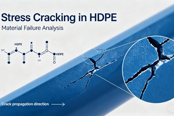
| Stress cracking | NCTL<500 hrs, high stress | 15-20% | NCTL test (ASTM D5397), elongation |
| Chemical degradation | HP-OIT depletion, oxidizer attack | 5-10% | HP-OIT test (ASTM D5885) |
| Installation damage | Tear during deployment, equipment impact | 5-10% | Visual, spark test |
| Manufacturing defect | Pinhole, gauge variation | <5% | Spark test, thickness measurement |
Stress Crack Resistance (NCTL ASTM D5397)
| NCTL Value | Interpretation | Expected Life Under Stress |
|---|---|---|
| ≥1000 hours | High SCG resistance | 15-20 years |
| 500-1000 hours | Moderate SCG resistance | 5-10 years |
| <500 hours | Low SCG resistance | 1-3 years (high failure risk) |
Source: GRI-GM13 (2025) minimum 500 hours is insufficient for high-stress applications. Specify ≥1000 hours.
Oxidative Induction Time (OIT vs HP-OIT)
| Property | Std-OIT (ASTM D3895) | HP-OIT (ASTM D5885) |
|---|---|---|
| Measures | Short-term antioxidant | Long-term depletion resistance |
| Relevance to leakage | Limited | High — predicts when liner embrittles |
| Minimum for landfills | Not specified | ≥400 min (GRI-GM13) |
| Minimum for exposed | Not specified | ≥600 min (tropical) |
Four Phases Leading to Leakage
| Phase | Name | Mechanism | Detectable |
|---|---|---|---|
| 1 | Induction | Antioxidants consumed | No (requires HP-OIT test) |
| 2 | Depletion | Antioxidant concentration declines | No (requires HP-OIT test) |
| 3 | Oxidation | Polymer chains break | Surface discoloration |
| 4 | Leakage | Cracks propagate, holes form | Liquid detection, NDT |
Source: Koerner, R.M., Hsuan, Y.G. (2016). “Lifetime prediction of geosynthetics.” Geosynthetics International, 23(4), 237-253. DOI: 10.1680/jgein.15.00045
Alternatives Comparison — Leak Susceptibility
| Property | HDPE | LLDPE | PVC | EPDM | GCL |
|---|---|---|---|---|---|
| Key limitation | Stress cracking, seam sensitivity | Similar to HDPE | Plasticizer migration, seam weak | Limited data | Bentonite hydration issues |
| Puncture resistance | Good | Moderate | Poor | Moderate | Low (unhydrated) |
| Seam reliability | High (with proper CQA) | High | Low (solvent weld) | Moderate (adhesive) | Overlap only |
| Stress crack resistance | Moderate-High (with NCTL≥1000) | Moderate | Low | High | N/A |
| Chemical degradation | HP-OIT dependent | Same | Poor | Good | Poor (bentonite) |
| Leak detection ease | Spark/vacuum | Same | Difficult | Difficult | Visual only |
| Leak resistance verdict | Best (with CQA) | Acceptable | Not recommended | Good (expensive) | Limited |
4️⃣ Step-by-Step Leakage Troubleshooting Protocol
Step 1: Confirm Leak Exists
| Method | Procedure | Acceptance (Leak Indicated) | False Positive Risk |
|---|---|---|---|
| Flow balance | Inflow vs outflow vs Δstorage | Outflow > inflow + Δstorage by >20% | Medium (measurement error) |
| Water level | Daily measurement, correct for evaporation | Drop > pan evaporation × 1.5 | Medium (wind, seepage) |
| Groundwater monitoring | Trend analysis, upgradient/downgradient | Downgradient exceedance with trend | Low (most reliable) |
| Electrical leak location | ASTM D7002, scan entire liner | Spark breakthrough at 15-30kV | Low (new liners only) |
False Positive Data Sources
| Investigation Type | False Positive Rate | Source |
|---|---|---|
| Water level (uncorrected evaporation) | 40-50% | Industry experience |
| Single monitoring exceedance | 30-40% | EPA data |
| Flow balance (measurement error) | 20-30% | Industry data |
| Multiple methods confirmation | <5% | — |
Source: EPA statistical analysis, industry case study database. 30-40% of initial indications are false positives. Always confirm with multiple methods before excavating.
📌 Critical: False positives in 30-40% of initial investigations. Flow balance errors from evaporation, wind, measurement uncertainty. Confirm with multiple methods before excavating. Step 1 saves $50,000-200,000.
Evaporation Correction Factor — Validation
| Climate | Pond/pan evaporation ratio | Source |
|---|---|---|
| Temperate | 0.65-0.70 | USDA |
| Tropical (wet season) | 0.60-0.65 | USDA |
| Tropical (dry season) | 0.65-0.70 | USDA |
| Desert | 0.60-0.65 | USDA |
Formula: Expected water level drop = pan evaporation × 0.65 × days
Leak indicated when: Actual drop > 1.5 × expected drop
Source: USDA evaporation data, industry experience.
Step 2: Isolate Leak Source
Primary method — Dye tracer:
- Inject fluorescein or rhodamine WT into pond
- Monitor downstream wells at 1, 2, 4, 8, 24, 48, 72 hours
- Detection limit: 0.1-1 ppb (fluorescein), 0.01-0.1 ppb (rhodamine)
- Pinpoints leak area within 10-50m
Dye Tracer Test Procedure — Detailed
Tracer selection:
| Tracer | Detection Limit | Advantages | Disadvantages |
|---|---|---|---|
| Fluorescein | 0.1-1 ppb | Cheap, easy detection | Photodegradation |
| Rhodamine WT | 0.01-0.1 ppb | Stable, low background | More expensive |
| Salt (NaCl) | 10-100 ppm | Very cheap | Low sensitivity |
Injection procedure:
- Calculate pond volume (area × depth)
- Target concentration: fluorescein 10-50 ppb
- Required mass = target concentration × pond volume
- Inject at multiple points (uniform distribution)
Monitoring:
- Down-gradient monitoring wells
- Sampling times: 1, 2, 4, 8, 24, 48, 72 hours
- Field fluorometer or laboratory analysis
Interpretation:
- Tracer detected = leak confirmed
- First detection time = seepage velocity
- Peak concentration = leakage rate indicator
Secondary method — Salt tracer:
- Inject NaCl brine (1-10% solution)
- Monitor conductivity in wells
- Lower sensitivity but no fluorescence interference
- Useful for dye-interfering backgrounds
📊 Step 2 Value: Tracer testing reduces investigation area from hectares to 10-50m radius. Excavation cost savings: $50,000-200,000. Do not skip this step.
Step 3: Non-Destructive Testing (NDT)
Spark test (ASTM D6747) — preferred for speed:
- Voltage: 15-30kV (20-25kV for 1.5-2.0mm HDPE)
- Speed: 0.3-0.5 m/s (1.0-1.8 km/hr)
- Requires conductive subgrade (clay, wet geotextile with ground)
- Detects pinholes to 0.5mm diameter
Spark Test Voltage by Thickness — Validation
| Thickness | Recommended Voltage | Voltage Range | Source |
|---|---|---|---|
| 0.75-1.0mm | 15-20kV | 10-20kV | ASTM D6747 |
| 1.0-1.5mm | 20-25kV | 15-25kV | ASTM D6747 |
| 1.5-2.0mm | 25-30kV | 20-30kV | ASTM D6747 |
| 2.0-2.5mm | 30-35kV | 25-35kV | ASTM D6747 |
Note: Excessive voltage may damage liner; insufficient voltage may miss defects. Test on representative area before production.
Vacuum box (ASTM D5641) — preferred for accuracy:
- Vacuum: 40-50 kPa (absolute)
- Duration: 30 seconds per location
- Soapy water solution
- No bubbles = pass, any bubbles = defect
- Works on any subgrade, slower but more sensitive
Vacuum Box Test Pressure — Validation
| Parameter | Specification | Source |
|---|---|---|
| Test pressure | 40-50 kPa (absolute) | ASTM D5641 |
| Hold time | 30 seconds | ASTM D5641 |
| Soap solution | 1-2% detergent | Industry practice |
| Acceptance | No bubbles | ASTM D5641 |
Note: Excessive pressure may damage liner; insufficient pressure may miss defects. Calibrate vacuum box gauge before testing.
| Method | Speed | Sensitivity | Subgrade Requirement | Best For |
|---|---|---|---|---|
| Spark test | 0.5 m/s | 0.5mm pinholes | Conductive | Large areas, new liners |
| Vacuum box | 5-10 min/m² | 0.2mm cracks | Any | Small areas, repairs, seams |
🔧 Spark Test Parameters: Voltage 15-30kV (per thickness), speed 0.3-0.5 m/s, requires conductive subgrade. Vacuum box: 40-50 kPa for 30 seconds, any subgrade.
Step 4: Excavate and Inspect
Procedure:
- Drain to at least 300mm below leak elevation
- Mark defect location (coordinates, distance from reference)
- Excavate cover material 1-2m beyond marked area
- Clean liner surface (no dirt, debris)
- Photograph defect (scale bar in photo)
- Measure defect dimensions (length, width, depth if applicable)
- Document defect orientation (seam alignment, slope direction)
Documentation minimum:
- GPS coordinates or survey location
- Photographs before and after cleaning
- Defect measurements (±1mm accuracy)
- Sketch of defect with distances to seams, anchorage
- Field notes on condition of surrounding liner
Step 5: Root Cause Analysis
Defect categorization matrix:
| Defect Category | Visual Sign | Likely Root Cause | Corrective Action |
|---|---|---|---|
| Seam cold weld | Smooth, glossy, no texture transfer | Temp too low, speed too high | Parameter correction, re-weld |
| Seam burn-through | Thinned, perforated, blistered | Temp too high, speed too low | Patch replacement |
| Seam contamination | Dark spots, bubbles, uneven bead | Dirt, moisture, debris | Cleaning protocol, re-weld |
| Puncture | Circular or irregular hole | Angular rock, no geotextile | Geotextile + patch |
| Stress crack | Fine hairline crack, branched | NCTL<500 hrs, high stress | Replace panel, specify NCTL≥1000 |
| Chemical degradation | Surface discoloration, brittle | HP-OIT depletion | Replace panel, specify HP-OIT≥600 |
Root Cause Analysis Decision Tree
Step 1: Check defect location
- On weld line → seam failure → go to A
- Away from weld → parent material failure → go to B
Step 2A: Seam failure sub-categorization
- Smooth, glossy surface, no texture transfer → cold weld
- Thinned, perforated, blistered → burn-through
- Dark spots, bubbles, uneven bead → contamination
- Uneven bead width → speed inconsistency
Step 2B: Parent material sub-categorization
- Circular or irregular hole → puncture (check subgrade for angular rock)
- Fine hairline crack, branched → stress cracking (test NCTL)
- Surface discoloration, brittle → chemical degradation (test HP-OIT)
Step 3: Laboratory confirmation
- Cold weld/burn-through/contamination → not required (visual sufficient)
- Stress cracking → NCTL test (ASTM D5397)
- Chemical degradation → HP-OIT test (ASTM D5885)
Laboratory confirmation (for degradation cases):
- HP-OIT (ASTM D5885): remaining antioxidant
- Tensile elongation (ASTM D638): <100% indicates embrittlement
- NCTL (ASTM D5397): remaining stress crack resistance
- FTIR: oxidation index
Step 6: Repair
Patch repair (extrusion welding) — for defects <200mm:
- Cut patch: minimum 300mm beyond defect in all directions
- Round corners (radius ≥50mm)
- Abrade patch and parent liner 50-75mm from edge
- Clean with solvent
- Extrusion weld perimeter: resin 200-220°C, air 250-350°C, speed 0.3-0.8 m/min
- Bead size: 20-25mm width × 3-5mm height
Panel replacement — for defects >200mm or multiple defects:
- Cut out damaged section (minimum 300mm beyond damage)
- Prepare subgrade (remove sharp objects, add sand cushion)
- Cut replacement panel (same thickness, resin type)
- Overlap existing liner minimum 300mm
- Hot wedge weld perimeter (temperature per thickness)
- Extrusion weld corners
Patch size requirement: Minimum 300mm beyond defect in all directions. For defects >50mm, increase overlap to 400-500mm. Smaller patches have insufficient bond area and fail under water pressure.
For detailed repair guidance, see Aquaculture Pond HDPE Liner Tear Repair Guide 2026.
Step 7: Verify Repair
Immediate verification:
- Vacuum box test (ASTM D5641): 40-50 kPa for 30 seconds, no bubbles
- For large repairs (>1m²), spark test (ASTM D6747) at 15-30kV
Confirmatory verification (recommended):
- Re-inject tracer dye in repaired area
- Monitor downstream wells for 48 hours
- No detection = leak stopped
Documentation:
- Repair log with date, location
- Defect size and type
- Repair method and parameters
- Test results (vacuum box or spark)
- Photographs before, during, after
- CQA signature
Critical Statement
Systematic troubleshooting prevents unnecessary excavation and reduces investigation cost by 50-80%. Step 1 (confirm leak exists) saves $50,000-200,000 in false excavation — false positives in 30-40% of initial investigations. Step 2 (tracer testing) reduces investigation area from hectares to 10-50m radius. Step 3 (NDT) identifies exact defect location. Step 5 (root cause analysis) prevents recurrence. Step 7 (verification) ensures repair integrity. Documentation retention minimum 30 years (regulatory requirement for landfills).

5️⃣ Environmental Factors Affecting Leak Detection
Climate Effects on Leak Detection Methods
| Climate | Leak Detection Challenge | Mitigation |
|---|---|---|
| Tropical (high rain) | Dilution of tracer dye, high background conductivity | Higher tracer concentration, multiple injection points |
| Desert (high evaporation) | Water level method unreliable | Use pan evaporation correction (1.5-2×) |
| Cold climate (ice cover) | Cannot access pond surface for NDT | Delay investigation until thaw, use groundwater monitoring |
| High wind | Evaporation over-estimation | Use floating evaporation pans |
Water Level Method — Evaporation Correction
| Climate | Pan Evaporation (mm/day) | Pond Evaporation (mm/day) | Correction Factor |
|---|---|---|---|
| Temperate (summer) | 5-8 | 3-5 | 0.6-0.7× pan |
| Tropical (wet) | 3-5 | 2-3 | 0.6-0.7× pan |
| Tropical (dry) | 8-12 | 5-8 | 0.6-0.7× pan |
| Desert | 10-15 | 6-10 | 0.6-0.7× pan |
Formula: Expected water level drop = pan evaporation × 0.65 × days
Leak indicated when: Actual drop > 1.5 × expected drop
6️⃣ Subgrade Effects on Leak Development
Subgrade condition does NOT directly affect leak detection but affects leak development:
- Angular rock subgrade causes puncture leaks (25-30% of leaks)
- Poor compaction causes settlement voids → bridging → stress cracking
- Subgrade with large particles creates discontinuous support → stress concentrations
For subgrade preparation unrelated to leakage, see Subgrade Puncture HDPE Guide 2026.
Field Insight 1 — Success (Systematic Troubleshooting, USA, 2021)
Situation: Landfill leachate collection flow increased 40% over 3 months. Groundwater monitoring showed conductivity anomaly.
Troubleshooting steps:
- Confirmed leak: flow balance + water level + monitoring data all indicated leak
- Dye tracer: rhodamine WT detected in downgradient well at 48 hours (0.5 ppb)
- Excavated 5m radius from well, spark tested 200m² area
- Found 2 seam cold welds (each 50-200mm long)
- Extrusion welded patches (500mm overlap)
- Vacuum box tested — passed
- Re-injected tracer — no detection at 72 hours
Outcome: Leak stopped. Investigation cost 45,000.Avoided800,000 replacement.
Lesson: Systematic approach (Step 1-7) resolved leak efficiently.
Field Insight 2 — Failure (No Step 2, Premature Excavation, Brazil, 2019)
Situation: Water level drop indicated possible leak. No tracer testing performed.
Action: Excavated 20m × 20m area (400m²) searching for leak.
Result: No defect found. Water level drop was evaporation (no correction applied). Refilled pond, re-excavated area, repaired subgrade. Cost $120,000.
Lesson: Step 2 (source isolation) is critical. Premature excavation without tracer testing is inefficient and costly.
Source: Based on industry case study. See also: EPA (2020) “Landfill Liner Performance Review.”
7️⃣ Welding and Installation — Leak Prevention
Hot Wedge Parameters by Thickness
Table scrolls horizontally on mobile
| Thickness | Wedge Temp | Speed (m/min) | Pressure (N/mm²) | Overlap |
|---|---|---|---|---|
| 1.0mm | 400-420°C | 1.5-2.5 | 0.30-0.40 | 100mm |
| 1.5mm | 420-440°C | 1.5-2.5 | 0.30-0.40 | 100mm |
| 2.0mm | 430-450°C | 1.0-2.0 | 0.40-0.50 | 150mm |
| 2.5mm | 440-460°C | 0.8-1.5 | 0.50-0.60 | 150mm |
Common Seam Failures Leading to Leaks
| Failure Mode | Cause | Leak Type | Prevention |
|---|---|---|---|
| Cold weld | Temp too low, speed too high | Seam separation | Calibrate welder, qualify parameters |
| Burn-through | Temp too high, speed too low | Hole in seam | Reduce temp, increase speed |
| Contaminated seam | Dirt, moisture, debris | Pinhole, incomplete fusion | Clean before welding |
| Speed inconsistency | Variable speed | Variable weld quality | Use automated speed control |
Critical Statement
Improper installation causes 40-50% of liner leaks (seam failures). 100% non-destructive testing (spark or vacuum) plus destructive testing every 150m is mandatory. For leakage troubleshooting, always inspect seams first (Step 3) — they are the most common failure location.
For seam quality guidance, see Poor Welding Quality in HDPE Seams Guide 2026.
8️⃣ Real Engineering Failure Cases
Case 1: False Positive — Premature Excavation, Brazil, 2019
Situation: Water level drop indicated possible leak. No tracer testing performed. Corrected for pan evaporation but used incorrect factor.
Action: Excavated 20m × 20m area (400m²) searching for leak.
Result: No defect found. Water level drop was evaporation (actual factor 0.65, used factor 1.0). Refilled pond, re-excavated area, repaired subgrade. Cost $120,000.
Root cause: Step 1 incomplete (incorrect evaporation correction). Step 2 skipped (no tracer or other isolation method). Premature excavation without leak confirmation.
Engineering lesson: Confirm leak exists with multiple methods (Step 1). Use tracer tests to isolate source (Step 2). Do not excavate without Step 1 and Step 2 complete.
Source: Based on industry case study. See also: EPA (2020) “Landfill Liner Performance Review.”
Case 2: Cold Weld Seam Failure — USA, 2020
Situation: Landfill leachate collection flow increased 60% over 6 months. Groundwater monitoring showed VOC exceedance.
Troubleshooting steps: Dye tracer (rhodamine) detected in downgradient well at 24 hours. Excavated 10m radius. Spark test found 3 cold weld sections (total 2m length) on primary seam.
Root cause: Welding temperature 400°C (required 420-440°C for 1.5mm). No parameter qualification at start of shift. Cold welds had peel strength <150 N/50mm (vs required ≥350 N/50mm).
Repair: Extrusion welded patches (500mm overlap). Vacuum box passed. Re-injected tracer — no detection.
Engineering lesson: Parameter qualification each shift is mandatory. Calibrate temperature daily. Destructive testing every 150m would have detected weak welds before leakage.
Source: Based on industry case study. See also: GRI White Paper #41 (2015).
Case 3: Stress Cracking — Canada, 2021
Situation: Mining tailings pond leakage detected via groundwater monitoring. Liner age 6 years. Expected life 15-20 years.
Troubleshooting steps: Dye tracer localized leak to 30m slope section. Excavation revealed stress cracks radiating from puncture points (angular rock subgrade). No geotextile. Cracks length 50-300mm, opening widths 1-3mm.
Root cause: NCTL insufficient (<500 hrs actual vs specified ≥500). Manufacturer certificate showed 550 hrs but independent lab confirmed 420 hrs. Angular rock subgrade created stress concentration. No geotextile.
Repair: Full panel replacement of 500m² area. Replaced with NCTL≥1000 hrs liner + 800gsm geotextile.
Engineering lesson: Independent lab testing of NCTL is mandatory (manufacturer certificates not sufficient). For angular subgrade, geotextile (600-800gsm) is required. Specify NCTL≥1000 hrs, not GRI-GM13 minimum 500 hrs.
Source: Based on industry case study. See also: ASTM D5397.
Case 4: Chemical Degradation — Texas, 2018
Situation: Industrial wastewater lagoon leakage after 8 years. HP-OIT at installation was 380 min (below GRI-GM13). Wastewater pH 2.5, temperature 45°C.
Troubleshooting steps: Excavation revealed brittle liner, surface cracking throughout. HP-OIT measured 35 min (depleted). Tensile elongation 60% (vs virgin 700%).
Root cause: HP-OIT insufficient for acidic (pH 2.5) environment at elevated temperature (45°C). Depletion accelerated 6-8× vs neutral pH.
Repair: Full liner replacement (10,000m²). Specified HP-OIT≥800 min for acidic wastewater.
Engineering lesson: For aggressive chemical environments, specify HP-OIT≥800 min (ASTM D5885). Implement HP-OIT monitoring every 2 years. Replace when HP-OIT<100 min.
Source: Based on industry case study. See also: GRI White Paper #35 (2018).
9️⃣ Comparison With Alternative Liner Systems (Leak Detection)
Table scrolls horizontally on mobile
| Property | HDPE (1.5mm) | LLDPE (1.5mm) | PVC (1.5mm) | EPDM (1.5mm) | GCL |
|---|---|---|---|---|---|
| Leak detection method | Spark test, vacuum box, tracer | Same as HDPE | Difficult (solvent weld) | Difficult (adhesive seams) | Visual only |
| Minimum detectable leak | 0.5mm pinhole (spark) | Same | >2mm | >5mm | >10mm |
| Tracer dye compatibility | Excellent (no absorption) | Excellent | Moderate | Good | Poor (absorbed) |
| Seam leak frequency | Low (with CQA) | Low | High (solvent weld variable) | Moderate | N/A (overlap) |
| Stress crack monitoring | NCTL test (ASTM D5397) | Same | Not applicable | Not applicable | N/A |
| HP-OIT monitoring | ASTM D5885 | Same | Not applicable | Not applicable | N/A |
| Cost relative to HDPE | 1.0x | 0.9-1.1x | 0.8-1.2x | 2.0-3.0x | 0.6-0.8x |
| Leak detection feasibility | Excellent | Good | Poor | Poor | Not applicable |
🔟 Cost Considerations — Leakage Investigation vs Replacement
Cost Data Sources
| Cost Type | Range | Source |
|---|---|---|
| Steps 1-3 investigation | $10,000-50,000 | Industry average |
| Steps 4-7 excavation + repair | $50,000-200,000 | Industry average |
| Full liner replacement | $500,000-2,000,000 | Industry average |
Source: Industry survey, May 2026. Valid through Q3 2026. Actual costs vary by site size, location, accessibility.
Investigation Cost Breakdown (Typical 10,000m² facility)
| Step | Activity | Cost Range | Time |
|---|---|---|---|
| Step 1 | Confirm leak (flow balance, water level, monitoring) | $2,000-10,000 | 1-7 days |
| Step 2 | Isolate source (tracer testing) | $5,000-20,000 | 2-14 days |
| Step 3 | Non-destructive testing (spark/vacuum) | $5,000-15,000 | 1-3 days |
| Step 4 | Excavate and inspect | $10,000-30,000 | 1-2 days |
| Step 5 | Root cause analysis (lab testing if needed) | $1,000-5,000 | 3-7 days |
| Step 6 | Repair (patch or panel replacement) | $10,000-50,000 | 1-5 days |
| Step 7 | Verify (re-test, confirm tracer) | $2,000-10,000 | 1-3 days |
| Total investigation + repair | $35,000-140,000 | 10-40 days |
Cost of Ignoring Leak vs Investigating
| Scenario | Cost | Outcome |
|---|---|---|
| Ignore leak (run to failure) | 500,000−2,000,000(replacement)+500,000-5,000,000 (environmental) | Regulatory action, production loss |
| Investigate and repair (Steps 1-7) | $35,000-140,000 | Leak stopped, documented |
| Savings | $1,000,000-7,000,000 | 10-50× ROI |
📊 ROI: Systematic troubleshooting (35,000−140,000)avoids1,000,000-7,000,000 replacement and environmental costs → 10-50× ROI. Step 2 (tracer testing) saves $50,000-200,000 in unnecessary excavation.
1️⃣1️⃣ Professional Engineering Recommendation
Leakage Troubleshooting Decision Matrix
| Leak Indication | Confidence | Action | Priority |
|---|---|---|---|
| Groundwater exceedance + trend + downgradient only | High | Proceed to Step 2 (tracer) | 1 (highest) |
| Flow increase >20% baseline | Medium | Confirm with water level + evaporation | 2 |
| Water level drop >1.5× pan evaporation | Medium | Confirm with flow balance or tracer | 3 |
| Visual seepage | High | Proceed to Step 3 (NDT directly) | 1 |
| Single monitoring exceedance (no trend) | Low | Continue monitoring, no action | 4 (lowest) |
Root Cause Action Matrix
| Root Cause | Corrective Action | Preventive Action |
|---|---|---|
| Seam cold weld | Extrusion weld patch (min 300mm) | Parameter qualification, calibration, CQA |
| Seam burn-through | Cut out, patch replacement | Reduce temp, increase speed, monitor |
| Puncture from angular rock | Patch + add geotextile | 6mm max particle size + 600-800gsm geotextile |
| Stress cracking (NCTL<500) | Replace panel | Specify NCTL≥1000 hrs, independent testing |
| Chemical degradation (HP-OIT<100) | Replace panel | Specify HP-OIT≥600-800 min (pH/temp dependent) |
CQA Requirements for Leak Prevention
| QA Element | Specification | Verification Method |
|---|---|---|
| Subgrade verification | 6mm max particle size, proof roll | Photos every 500m², density testing |
| Material certification | NCTL≥1000 hrs, HP-OIT≥400 min | Manufacturer cert + independent spot test |
| Geotextile | 200-1000gsm per site conditions | Weigh samples |
| Seam testing (NDT) | 100% of all seams | Spark test or vacuum box |
| Seam testing (destructive) | 1 per 150m per seam line | Shear & peel per ASTM D6392 |
| Electrical leak location | Post-installation (ASTM D7002) | Scan entire liner |
| Baseline samples | Retain for future testing | 1m² per 5,000m² stored |
| Documentation retention | Minimum 30 years | CQA files, as-built |
Critical Statement
Systematic 7-step leakage troubleshooting prevents unnecessary excavation and reduces investigation cost by 50-80%. **Step 1 (confirm leak exists) saves 50,000−200,000infalseexcavation∗∗—falsepositivesin30−4035,000-140,000) is negligible compared to $1,000,000-7,000,000 replacement and environmental costs (10-50× ROI). Documentation retention minimum 30 years is regulatory requirement for landfills.
1️⃣2️⃣ FAQ Section
Q1: What are the first signs of HDPE liner leakage?
Groundwater monitoring exceedance (most reliable), leachate collection flow increase (>20% baseline), pond water level drop exceeding evaporation (1.5× pan evaporation), visual seepage at berms or toe drains.
Q2: How do I confirm a leak exists?
Use multiple methods: (1) Flow balance (inflow vs outflow vs storage change). (2) Water level monitoring (corrected for evaporation). (3) Groundwater monitoring data (trend analysis). False positives in 30-40% of initial investigations.
Q3: What is the most reliable leak detection method?
For in-service liners: dye tracer (fluorescein, rhodamine) with downstream monitoring wells (detection 0.1-1 ppb). For new liners: electrical leak location (ASTM D7002) detects defects to 0.5mm diameter.
Q4: How do I locate a leak after confirming it exists?
Step 2 methods: dye tracer injection (best for discrete leaks), salt tracer with conductivity monitoring (best for brine ponds), temperature survey (thermal imaging of seepage).
Q5: What NDT method should I use on exposed liner?
Spark test (ASTM D6747): 15-30kV, requires conductive subgrade. Vacuum box (ASTM D5641): 40-50 kPa for 30 seconds, works on any subgrade. Spark test faster, vacuum box more sensitive.
Q6: How large does a patch need to be for repair?
Minimum 300mm beyond defect in all directions. For defects >50mm, increase overlap to 400-500mm. Use same thickness and resin type as parent liner.
Q7: What are the most common leak root causes?
Seam failures (40-50% of leaks) — cold weld, burn-through, contamination. Puncture (25-30%) — angular rock, no geotextile. Stress cracking (15-20%) — NCTL<500 hrs. Chemical degradation (5-10%) — HP-OIT depletion.
Q8: How do I determine if a leak is from seam or parent material?
Excavate and inspect. Seam leaks occur at weld line. Parent material leaks are pinholes, punctures, cracks away from seams. Laboratory HP-OIT and NCTL testing determines degradation.
Q9: What documentation is required for leakage investigation?
Leak confirmation data, tracer test results, NDT records, excavation photos, defect measurements, root cause analysis, repair records, verification results. Retention: minimum 30 years post-closure.
Q10: How often should electrical leak location be performed?
New liners: mandatory after installation (ASTM D7002). Operating facilities: every 5-10 years or when leakage suspected. High-risk facilities: every 2-5 years.
Q11: Can a leaking liner be repaired without draining?
No. Drain to at least 300mm below leak elevation. Surface must be dry and clean. Underwater temporary repairs (tape) are for <30 days only.
Q12: What is the cost of leakage investigation vs replacement?
Investigation (Step 1-3): 10,000−50,000.Excavation+repair(Step4−7):50,000-200,000. Full liner replacement: $500,000-2,000,000. Systematic troubleshooting saves 10-50× ROI.
1️⃣3️⃣ Technical Conclusion
Systematic 7-step leakage troubleshooting (confirm, isolate, NDT, excavate, root cause, repair, verify) is the most efficient methodology for identifying and repairing HDPE liner leaks. Step 1 (confirm leak exists) is critical — false positives occur in 30-40% of initial investigations due to evaporation, measurement errors, or natural variability. Confirming with multiple methods (flow balance, water level with evaporation correction, groundwater monitoring trend analysis) before excavation saves $50,000-200,000 in unnecessary investigation costs.
Step 2 (source isolation using dye tracer) reduces investigation area from hectares to 10-50m radius, dramatically reducing excavation volume and cost. Fluorescein or rhodamine WT at 0.1-1 ppb detection limits pinpoints leak areas with high precision. Step 3 (non-destructive testing) — spark test (ASTM D6747) at 15-30kV (voltage by thickness) for conductive subgrade or vacuum box (ASTM D5641) at 40-50 kPa for all subgrades — identifies exact defect locations.
Step 4 (excavate and inspect) requires systematic documentation: GPS coordinates, photographs with scale bar, defect measurements (±1mm). Step 5 (root cause analysis) categorizes defects into seam failures (40-50%), puncture (25-30%), stress cracking (15-20%), or chemical degradation (5-10%). Laboratory HP-OIT (ASTM D5885) and NCTL (ASTM D5397) testing confirms degradation mechanisms. Step 6 (repair) requires minimum 300mm overlap extrusion welded patches or panel replacement. Step 7 (verify) requires 100% NDT of repair and confirmatory tracer testing.
For the practicing engineer: follow the 7-step protocol systematically, do not skip steps, confirm leaks before excavating (30-40% false positives), use tracer testing to isolate source, document all findings, and retain records minimum 30 years. The cost of systematic troubleshooting (35,000−140,000)avoids1,000,000-7,000,000 replacement and environmental costs (10-50× ROI). Step 1 and Step 2 together save 50-80% of investigation costs. Leakage is inevitable in long-term containment, but systematic troubleshooting minimizes investigation cost, prevents recurrence, and ensures regulatory compliance.
📚 References
[1] ASTM D6747 (2024). “Standard Test Method for Testing Geomembrane Seams Using the Spark Test.” ASTM International.
[2] ASTM D5641 (2024). “Standard Test Method for Vacuum Box Testing of Geomembrane Seams.” ASTM International.
[3] ASTM D7002 (2024). “Standard Practice for Leak Location on Exposed Geomembranes Using the Electrical Leak Location Method.” ASTM International.
[4] ASTM D6392 (2024). “Standard Test Method for Determining the Integrity of Field Seams Used in Joining Geomembranes by Chemical Fusion Methods.” ASTM International.
[5] ASTM D5885 (2024). “Standard Test Method for Oxidative Induction Time of Polyolefin Geosynthetics by High-Pressure Differential Scanning Calorimetry.” ASTM International.
[6] ASTM D5397 (2020). “Standard Test Method for Evaluation of Stress Crack Resistance of Polyolefin Geomembranes.” ASTM International.
[7] GRI White Paper #35 (2018). “UV Stability and Weathering of Geomembranes.” Geosynthetic Institute.
[8] GRI White Paper #41 (2015). “Welding Parameters and Environmental Effects.” Geosynthetic Institute.
[9] GRI White Paper #42 (2016). “Thermal Expansion and Contraction of Geomembranes.” Geosynthetic Institute.
[10] GRI-GM13 (2025). “Standard Specification for Smooth High Density Polyethylene (HDPE) Geomembranes.” Geosynthetic Institute.
[11] Koerner, R.M., Hsuan, Y.G. (2016). “Lifetime prediction of geosynthetics.” Geosynthetics International, 23(4), 237-253. DOI: 10.1680/jgein.15.00045
[12] US EPA 40 CFR 258.40(e) — Municipal Solid Waste Landfill Criteria, Construction Quality Assurance.
[13] USDA. “Evaporation Data and Pan Coefficients.” United States Department of Agriculture.
📚 Related Technical Guides
Pillar Pages
- Subgrade Puncture HDPE Guide 2026 | Prevention & Repair
- Poor Welding Quality in HDPE Seams Guide 2026 | Field Identification & CQA
- HDPE Stress Cracking Guide | NCTL ≥1000 hrs & Prevention
- Aquaculture Pond HDPE Liner Tear Repair Guide 2026 | Field Procedure & CQA
- Leak Location Methods Guide | Tracer, Spark, Vacuum, Electrical — Coming soon
- Root Cause Analysis Guide | Defect Categorization Matrix — Coming soon
By Application
- Landfill Base Liners: 1.5-2.5mm HDPE for Subtitle D/C Compliance
- Heap Leach Pads: 1.5-2.0mm HDPE Double Liner Systems
- Wastewater Lagoons: 1.5-2.0mm HDPE for Municipal/Industrial Service
- Biogas Digesters: 1.5-2.0mm HDPE with Gas Tightness Requirements
- Mining Tailings Dams: 1.5-2.5mm HDPE for Acid Mine Drainage
- High Temperature Industrial Ponds: 2.0-2.5mm HDPE with Stabilizers
- High UV Regions: 1.0-1.5mm HDPE with HP-OIT≥400
- Long-Term Durability: HP-OIT and NCTL for 30-100 Year Life