HDPE Liner Failures from Excessive Loading 2026 | Mechanisms & Prevention
Failure Analysis 2026-09-16
Author: Senior Geomembrane Engineer, P.E. — 15+ years field experience in landfill, heap leach, and tailings liner design, loading analysis, and failure investigation across temperate, tropical, and cold climates
Reviewer: Geosynthetics Materials Specialist
Last Updated: July 8, 2026
Read Time: 13 minutes
📅 Review Cycle: This guide is updated quarterly. Last verified: July 8, 2026
📋 Executive Summary — For Engineers in a Hurry
- Excessive loading is a significant cause of liner failure, accounting for 10–20% of all containment system failures through puncture, tensile overstress, and creep deformation
- Overburden pressures of 500–1,500 kPa are common in deep landfills and tailings facilities, creating stresses that can exceed liner capacity
- Critical puncture pressure for 2.0mm HDPE is approximately 1,000–1,500 kPa on smooth subgrade, reducing to 300–500 kPa on angular subgrade
- Creep deformation under sustained loading can reduce liner thickness by 10–20% over 10–30 years, compromising barrier integrity
- Prevention requires proper subgrade preparation (≤ 6mm particles, ≥ 95% compaction), geotextile protection, and design for expected loading conditions
- Thicker liners provide marginal benefit under excessive loading — subgrade preparation and stress distribution are more critical than thickness
⚠️ Critical Engineering Statement — Subgrade Preparation > Liner Thickness for Loading Resistance
Under excessive loading, liner failure typically occurs at subgrade irregularities, not through the liner itself. Proper subgrade preparation is more effective than increased thickness.
- Subgrade preparation (≤ 6mm particles) reduces puncture risk by 70–90% compared to unprepared subgrade
- Geotextile protection distributes stress from loading, reducing puncture risk by 60–80%
- Thicker liners provide marginal improvement — 2.5mm liner offers only 20–30% greater puncture resistance than 2.0mm under loading
- Creep deformation occurs regardless of thickness — sustained loading causes thinning in all HDPE grades
- Prevention requires addressing both stress concentration (subgrade) and sustained stress (creep)
A 1.5mm liner on a prepared subgrade with geotextile protection will outperform a 2.5mm liner on an unprepared subgrade under excessive loading. Subgrade preparation and stress distribution outweigh liner thickness for loading resistance.
📑 Table of Contents
1️⃣ Search Intent Introduction
2️⃣ Common Engineering Questions About Excessive Loading Failures
3️⃣ Why HDPE Is Used — Material Science Focus
4️⃣ Loading Conditions and Stress Analysis
5️⃣ Puncture Mechanisms Under Loading
6️⃣ Creep Deformation Under Sustained Loading
7️⃣ Subgrade Preparation and Stress Distribution
8️⃣ Real Engineering Failure Cases
9️⃣ Comparison With Alternative Liner Systems
🔟 Prevention Strategies and Design Requirements
1️⃣1️⃣ Professional Engineering Recommendation
1️⃣2️⃣ FAQ Section
1️⃣3️⃣ Technical Conclusion
1️⃣ Search Intent Introduction
This guide addresses the engineering question of how excessive loading damages HDPE liners and how to prevent this failure mechanism through design, subgrade preparation, and protective measures. The primary audience includes geotechnical design engineers, EPC contractors, environmental regulators, facility owners, and CQA engineers evaluating liner systems where high overburden pressures create puncture and creep risks.
Understanding loading mechanisms is essential for subgrade preparation, geotextile specification, thickness selection, and monitoring program design. This is not an introductory overview — it is a data-driven engineering reference for professionals designing, installing, and monitoring containment liners where overburden pressures can exceed liner capacity.
Real-world loading conditions that create liner failure risk include:
- ✅ Deep landfills — waste heights of 30–60m creating overburden pressures of 450–900 kPa
- ✅ Tailings facilities — tailings depths of 20–50m creating pressures of 300–750 kPa
- ✅ Heap leach pads — ore heights of 10–40m creating pressures of 150–600 kPa
- ✅ Wastewater lagoons — sludge depths of 5–15m creating pressures of 50–150 kPa
- ✅ Equipment traffic — construction and operational equipment creating point loads
- ✅ Rapid placement — excessive loading rates causing differential stress
2️⃣ Common Engineering Questions About Excessive Loading Failures
Q1: How much load can an HDPE liner withstand?
Puncture resistance is the limiting factor. A 2.0mm liner on smooth subgrade can withstand 1,000–1,500 kPa before puncture. On angular subgrade (> 20mm particles), puncture occurs at 300–500 kPa. Tensile capacity is 20–25 MPa, but stress concentrations reduce this.
Q2: What is the primary failure mechanism from loading?
The primary failure mechanism is puncture at subgrade irregularities. Stress concentration at particles or protrusions exceeds the liner’s puncture resistance. Creep deformation under sustained loading is a secondary mechanism.
Q3: How does subgrade particle size affect loading resistance?
Particle size is the critical factor. GRI-GM13 requires ≤ 9.5mm particles. Recommend ≤ 6mm for high-load applications. Angular particles create stress concentrations 2–5x higher than rounded particles.
Q4: Does thickness increase loading resistance?
Thicker liners provide modest improvement (20–30% for each 0.5mm increase). However, subgrade preparation is far more effective. A 1.5mm liner on prepared subgrade outperforms a 2.5mm liner on unprepared subgrade.
Q5: What is creep deformation and how does it affect liners?
Creep is time-dependent deformation under sustained load. Under 500–1,000 kPa loading, HDPE liners can thin by 10–20% over 10–30 years. This reduces puncture resistance and barrier integrity.
Q6: How does geotextile protect against loading damage?
Geotextile (400–600 gsm) distributes stress from loading over a larger area. This reduces stress concentration at subgrade particles. Puncture risk reduction is 60–80% with 400–600 gsm geotextile.
Q7: What is the role of subgrade compaction in loading resistance?
Compaction (≥ 95% Standard Proctor) ensures uniform load distribution and prevents differential settlement. It also reduces void spaces that create bridging stress concentrations.
Q8: How can loading damage be monitored?
Monitoring methods include: settlement plates, pressure cells beneath the liner, strain gauges on the liner, and visual inspection of exposed areas. Leak location surveys can detect failure points.
Q9: Can loading-damaged liners be repaired?
Repair depends on damage extent. Localised punctures can be patched. Extensive creep deformation or multiple punctures may require section replacement. Prevention is far more cost-effective.
Q10: What is the maximum recommended loading rate?
Maximum loading rate is typically 1–3m per month. Rapid placement creates differential stress and can exceed liner capacity. Controlled placement with monitoring is recommended.
3️⃣ Why HDPE Is Used — Material Science Focus
HDPE dominates containment liner applications due to its excellent chemical resistance, low permeability, high tensile strength, and weldability. However, its puncture resistance and creep behaviour are critical factors in loading performance.
Puncture Resistance (ASTM D4833): HDPE puncture resistance is typically 300–600 N for 1.5–2.5mm liners. Under loading, puncture resistance is reduced by stress concentration at subgrade particles. Puncture pressure ranges from 300–1,500 kPa depending on subgrade conditions.
Tensile Strength and Loading Stress: HDPE tensile strength is approximately 20–25 MPa. Loading creates compressive stress on the liner, but this stress is transferred to the subgrade. Tensile stress occurs at subgrade irregularities where the liner drapes over particles.
Creep Behaviour: HDPE exhibits viscoelastic behaviour under sustained loading. Creep deformation causes thinning at stress concentration points. Creep rate is temperature-dependent (doubles per 10°C). Thinning of 10–20% is typical over 10–30 years.
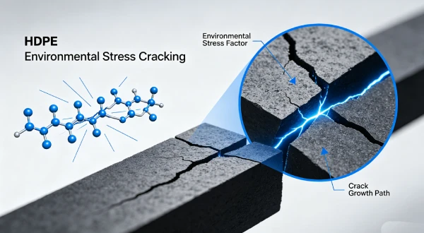
Stress Crack Resistance (NCTL per ASTM D5397): Loading-induced stress concentrations can initiate ESC. Resins with NCTL ≥ 1000 hours provide greater resistance to stress cracking from loading stress. GRI-GM13 requires NCTL ≥ 500 hours.
Tensile Modulus and Stress Distribution: HDPE tensile modulus (E ≈ 800–1000 MPa) determines stress distribution under loading. Higher modulus liners distribute stress more uniformly. Thicker liners have higher modulus but similar stress levels.
Carbon Black Content: Carbon black (2–3%) provides UV protection but does not affect loading resistance. Proper dispersion (ASTM D5596 rating ≥ 1) ensures uniform properties.
Alternatives Comparison: HDPE vs Other Liner Materials for Loading Resistance
| Property | HDPE | LLDPE | PVC | EPDM | GCL |
|---|---|---|---|---|---|
| Puncture resistance (N) | 300–600 | 200–400 | 100–200 | 100–300 | N/A |
| Puncture pressure (kPa)* | 500–1,500 | 300–1,000 | 200–500 | 200–400 | N/A |
| Creep resistance | Good | Moderate | Poor | Fair | N/A |
| Stress crack resistance | Good (requires NCTL) | Moderate | Poor (embrittles) | Fair | N/A |
| Subgrade preparation required | Critical | Critical | Important | Important | N/A |
| Geotextile protection required | Yes | Yes | Yes | Yes | No |
| Loading tolerance | Good | Moderate | Poor | Fair | N/A |
| Cost relative to HDPE | 1.0x | 1.0–1.1x | 1.2–1.5x | 2.0–3.0x | 0.6–0.8x |
*Based on smooth subgrade conditions
4️⃣ Loading Conditions and Stress Analysis
Understanding loading conditions is essential for designing liners that resist puncture and creep.
Overburden Pressure Calculation:
P = γ × H
Where:
- P = Overburden pressure (kPa)
- γ = Unit weight of material (kN/m³)
- H = Height of material (m)
Typical Overburden Pressures:
| Application | Material Density (kN/m³) | Typical Height (m) | Pressure (kPa) |
|---|---|---|---|
| MSW landfill | 10–15 | 30–60 | 300–900 |
| Hazardous waste | 15–20 | 10–30 | 150–600 |
| Heap leach ore | 15–20 | 10–40 | 150–800 |
| Tailings | 15–18 | 20–50 | 300–900 |
| Wastewater sludge | 10–12 | 5–15 | 50–180 |
Table scrolls horizontally on mobile
Stress Concentration Factors:
| Subgrade Feature | Stress Concentration Factor |
|---|---|
| Smooth subgrade, no particles | 1x (baseline) |
| Rounded particle < 6mm | 2–3x |
| Angular particle < 6mm | 3–5x |
| Rounded particle 6–20mm | 4–6x |
| Angular particle 6–20mm | 5–10x |
| Angular particle > 20mm | 10–20x |
Table scrolls horizontally on mobile
Critical Load Thresholds:
| Liner Thickness | Smooth Subgrade | ≤ 6mm Particles | Angular > 20mm |
|---|---|---|---|
| 1.5mm | 1,200–1,500 kPa | 600–900 kPa | 300–500 kPa |
| 2.0mm | 1,500–1,800 kPa | 800–1,200 kPa | 400–600 kPa |
| 2.5mm | 1,800–2,100 kPa | 1,000–1,500 kPa | 500–800 kPa |
Table scrolls horizontally on mobile
5️⃣ Puncture Mechanisms Under Loading
Loading creates puncture risk through multiple mechanisms.
Mechanism 1: Stress Concentration at Particles:
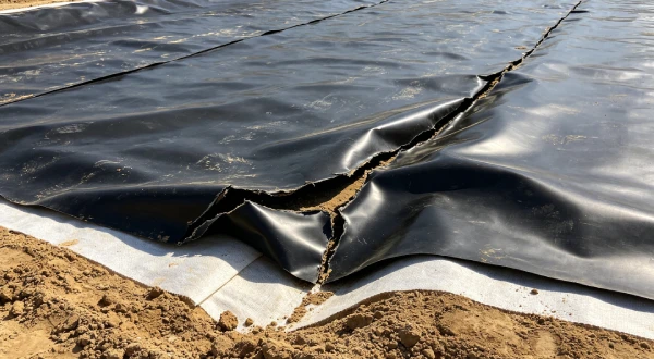
Overburden pressure transfers load through the liner to subgrade particles. Stress concentration at particle tips exceeds puncture resistance. The liner is pressed onto the particle, creating localised stress.
Mechanism 2: Bridging Over Voids:
The liner spans voids between particles or soft spots. Loading causes the liner to drape over the void, creating tensile stress at the void edges. Puncture occurs at the void edge or particle contact point.
Mechanism 3: Differential Settlement:
Uneven loading or subgrade settlement creates differential stress. The liner is pulled into tension over settling areas. Puncture or tear occurs at stress concentration points.
Mechanism 4: Creep Thinning:
Sustained loading causes creep deformation at stress concentration points. Liner thickness reduces by 10–20% over time. Thinner liner has lower puncture resistance, leading to failure.
Puncture Pressure Reduction Factors:
| Factor | Puncture Pressure Reduction |
|---|---|
| Particle size > 6mm | 40–60% |
| Angular particles | 30–50% |
| No geotextile | 40–60% |
| Void bridging | 50–70% |
| Creep thinning (10%) | 15–25% |
Table scrolls horizontally on mobile
6️⃣ Creep Deformation Under Sustained Loading
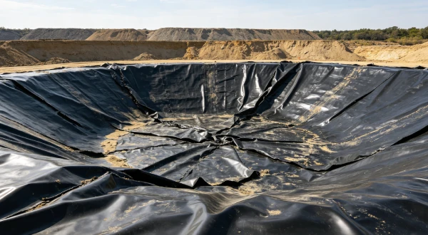
Creep is time-dependent deformation under sustained loading that reduces liner thickness over time.
Creep Behaviour:
HDPE exhibits viscoelastic behaviour with three creep stages:
- Primary creep: Decreasing strain rate (months to years)
- Secondary creep: Constant strain rate (years to decades)
- Tertiary creep: Increasing strain rate leading to failure (decades)
Creep Strain vs Time:
| Loading (kPa) | Primary Creep | Secondary Creep | Total Creep (30 years) |
|---|---|---|---|
| 200 | 1–2% | 0.5–1% | 2–4% |
| 500 | 3–5% | 1–2% | 5–8% |
| 1,000 | 6–10% | 2–4% | 10–15% |
| 1,500 | 10–15% | 3–5% | 15–20% |
Table scrolls horizontally on mobile
Thickness Reduction from Creep:
| Initial Thickness | 10-year Thinning | 30-year Thinning |
|---|---|---|
| 1.5mm | 0.05–0.10mm (3–7%) | 0.10–0.20mm (7–13%) |
| 2.0mm | 0.05–0.15mm (3–8%) | 0.15–0.30mm (8–15%) |
| 2.5mm | 0.05–0.20mm (2–8%) | 0.20–0.40mm (8–16%) |
Table scrolls horizontally on mobile
Temperature Effects on Creep:
| Temperature | Creep Rate (Relative to 20°C) |
|---|---|
| 10°C | 0.5x (slower) |
| 20°C | 1x (baseline) |
| 30°C | 2–3x |
| 40°C | 4–8x |
Table scrolls horizontally on mobile
7️⃣ Subgrade Preparation and Stress Distribution
Subgrade preparation is the most critical factor in preventing loading-induced liner damage.
Subgrade Compaction Requirements:
| Parameter | Requirement | Purpose |
|---|---|---|
| Compaction | ≥ 95% Standard Proctor | Uniform load distribution |
| Particle size | ≤ 6mm | Eliminate puncture points |
| Moisture content | Optimum ± 2% | Achievable compaction |
| Lift thickness | ≤ 200mm | Uniform compaction |
| Proof rolling | Visual + testing | Identify soft spots |
Geotextile Protection for Loading Resistance:
| Geotextile Weight | Stress Distribution | Puncture Reduction |
|---|---|---|
| No geotextile | Poor | 0% |
| 200–300 gsm | Moderate | 30–50% |
| 400 gsm | Good | 60–80% |
| 600 gsm | Excellent | 80–90% |
Table scrolls horizontally on mobile
Void and Soft Spot Management:
- ✅ Identify voids and soft spots through proof-rolling
- ✅ Fill voids with compacted soil (≥ 95% Standard Proctor)
- ✅ Treat soft spots with removal and replacement
- ✅ Over-excavate to 300mm below grade for soft spots
Loading Rate Management:
| Loading Rate | Risk Level | Mitigation |
|---|---|---|
| < 1m/month | Low | Standard monitoring |
| 1–3m/month | Moderate | Settlement monitoring |
| 3–5m/month | High | Strain monitoring |
| > 5m/month | Extreme | Immediate monitoring + controls |
Table scrolls horizontally on mobile
8️⃣ Real Engineering Failure Cases
Case 1: Puncture from Angular Subgrade — US Midwest Landfill, 2017
Specification used: 2.0mm HDPE, no geotextile. Subgrade particles up to 50mm (exceeding specification). Waste height 40m (approximately 600 kPa).
Observed failure: Multiple punctures at subgrade particle locations after 2 years. Punctures 5–20mm diameter. Leakage through punctures.
Timeline:
2017: 2.0mm HDPE installed, no geotextile, subgrade particles > 50mm
2017-2019: Waste placement to 40m (600 kPa)
2019: Multiple punctures detected, leakage
2019-2020: Subgrade remediation and liner repair
Cost: $3.2M (subgrade remediation + liner repair + monitoring)
Root cause: Subgrade particles exceeded specification (50mm vs required ≤ 6mm). Loading of 600 kPa created stress concentration at particles. Stress concentration factors of 5–10x exceeded puncture resistance.
Engineering lesson: Enforce subgrade particle size ≤ 6mm for high-load applications. Geotextile protection required for all liners. Compaction testing and proof-rolling at 100m intervals.
Case 2: Creep Deformation Failure — Australian Tailings Facility, 2019
Specification used: 2.0mm HDPE, 400 gsm geotextile. Tailings height 45m (approximately 700 kPa). Sustained loading for 10 years.
Observed failure: Creep thinning of 15% at liner base. Puncture at thinned locations after 10 years. Leakage through punctures.
Timeline:
2019: 2.0mm HDPE installed, 400gsm geotextile
2019-2029: Tailings placement to 45m (700 kPa)
2029: Creep thinning 15% detected
2029: Puncture at thinned locations, leakage
2029-2030: Liner replacement
Cost: $4.5M (liner replacement + tailings removal + remediation)
Root cause: Sustained loading of 700 kPa for 10 years caused creep thinning of 15% (0.3mm reduction). Thinning reduced puncture resistance by 20–30%. Subgrade particles (although ≤ 6mm) caused stress concentration at thinned areas.
Engineering lesson: Consider creep in design for high-load, long-term applications. Thicker liner (2.5mm) or geotextile reinforcement. Monitoring of liner thickness via exhumed samples.
Case 3: Rapid Loading Damage — South American Heap Leach Pad, 2020
Specification used: 2.0mm HDPE, 400 gsm geotextile. Ore placement rate of 8m/month (excessive). Total ore height 30m (450 kPa).
Observed failure: Differential settlement and puncture at ore placement fronts after 18 months. Multiple punctures at loading fronts. Leakage through punctures.
Timeline:
2020: 2.0mm HDPE installed, 400gsm geotextile
2020-2021: Rapid ore placement (8m/month)
2021: Differential settlement, punctures at loading fronts
2021: Leakage detected
2021-2022: Loading rate reduced, liner repairs
Cost: $2.8M (liner repairs + loading rate reduction + monitoring)
Root cause: Rapid ore placement (8m/month) created differential stress at loading fronts. The liner experienced unequal loading, causing bridging and stress concentration at subgrade particles. Puncture occurred at stress concentration points.
Engineering lesson: Limit loading rate to ≤ 3m/month. Monitor settlement and liner stress during loading. Geotextile reinforcement at loading fronts. Control loading sequence to minimise differential stress.
Failure Case Cost Summary
| Case | Location | Failure Mode | Cost | Primary Lesson |
|---|---|---|---|---|
| Case 1 | US Midwest | Puncture from angular subgrade | $3.2M | Subgrade ≤ 6mm, geotextile required |
| Case 2 | Australia | Creep deformation | $4.5M | Consider creep in design, thicker liner |
| Case 3 | South America | Rapid loading damage | $2.8M | Limit loading rate ≤ 3m/month |
9️⃣ Comparison With Alternative Liner Systems
| Property | HDPE (2.0mm) | LLDPE (1.5mm) | PVC (1.5mm) | EPDM (1.5mm) | GCL |
|---|---|---|---|---|---|
| Puncture resistance (N) | 400–600 | 200–400 | 100–200 | 100–300 | N/A |
| Puncture pressure (kPa)* | 1,500–1,800 | 1,000–1,500 | 500–800 | 300–600 | N/A |
| Creep resistance | Good | Moderate | Poor | Fair | N/A |
| Stress crack resistance | Good (requires NCTL) | Moderate | Poor (embrittles) | Fair | N/A |
| Subgrade preparation required | Critical | Critical | Important | Important | N/A |
| Geotextile protection required | Yes | Yes | Yes | Yes | No |
| Loading tolerance | Good | Moderate | Poor | Fair | N/A |
| Long-term loading performance | Good | Moderate | Poor | Fair | N/A |
| Containment application suitability | ✅ Recommended | ⚠️ Limited | ❌ Not recommended | ⚠️ Limited (cost) | ✅ Composite use |
| Cost relative to HDPE | 1.0x | 1.0–1.1x | 1.2–1.5x | 2.0–3.0x | 0.6–0.8x |
Table scrolls horizontally on mobile
🔟 Prevention Strategies and Design Requirements
Subgrade Preparation:
- ✅ Compaction: ≥ 95% Standard Proctor
- ✅ Particle size: ≤ 6mm
- ✅ Proof-rolling: Identify soft spots and voids
- ✅ Void filling: Fill all voids with compacted soil
Geotextile Protection:
- ✅ Minimum weight: 400 gsm (600 gsm for high load)
- ✅ Type: Nonwoven needle-punched
- ✅ Installation: Directly beneath HDPE liner
- ✅ Overlap: 300mm minimum
Liner Design:
- ✅ Thickness: 2.0mm standard, 2.5mm for > 500 kPa
- ✅ NCTL: ≥ 1000 hours for critical applications
- ✅ Geotextile: Required for all loading applications
Loading Management:
- ✅ Maximum rate: 3m/month
- ✅ Monitoring: Settlement plates, pressure cells
- ✅ Controlled placement: Uniform loading
- ✅ Inspection: Weekly during loading
CQA Requirements:
- ✅ Subgrade verification: Compaction testing at 100m intervals
- ✅ Particle size verification: Sieve analysis
- ✅ Geotextile verification: Weight, type, installation
- ✅ Loading monitoring: Regular readings
- ✅ Documentation: All records for lifetime of facility
1️⃣1️⃣ Professional Engineering Recommendation
Loading Risk Management Matrix:
| Loading Risk Level | Liner Thickness | Geotextile | Subgrade Prep | Loading Rate |
|---|---|---|---|---|
| Low: < 200 kPa, uniform loading | 1.5mm | 400 gsm | ≤ 6mm particles | < 3m/month |
| Moderate: 200–500 kPa, variable loading | 2.0mm | 400–600 gsm | ≤ 6mm + proof-rolling | < 2m/month |
| High: 500–1,000 kPa, high loading | 2.0–2.5mm | 600 gsm | ≤ 6mm + compaction testing | < 1m/month |
| Extreme: > 1,000 kPa, critical application | 2.5mm | 600 gsm + reinforcement | ≤ 6mm + monitoring | < 1m/month + monitoring |
Table scrolls horizontally on mobile
When to Specify Enhanced Loading Protection:
- Deep landfills (> 30m waste height)
- High-density tailings (> 500 kPa)
- Critical containment (groundwater protection)
- Design life > 50 years
- Variable loading conditions
- Limited post-placement access for monitoring
Critical Design Considerations:
- Subgrade particle size (≤ 6mm)
- Geotextile protection (≥ 400 gsm)
- Loading rate control (≤ 3m/month)
- Creep in long-term design
- Monitoring program development
Quality Assurance Requirements:
- ✅ Subgrade verification: 100% proof-rolling, compaction testing
- ✅ Particle size verification: Sieve analysis at 100m intervals
- ✅ Geotextile verification: Weight, type, installation
- ✅ Loading monitoring: Settlement plates, pressure cells
- ✅ Documentation: All records for lifetime of facility
1️⃣2️⃣ FAQ Section
Q1: How much load can an HDPE liner withstand?
Puncture resistance is the limiting factor. A 2.0mm liner on smooth subgrade can withstand 1,000–1,500 kPa before puncture. On angular subgrade (> 20mm particles), puncture occurs at 300–500 kPa.
Q2: What is the primary failure mechanism from loading?
The primary failure mechanism is puncture at subgrade irregularities. Stress concentration at particles or protrusions exceeds the liner’s puncture resistance. Creep deformation under sustained loading is a secondary mechanism.
Q3: How does subgrade particle size affect loading resistance?
Particle size is the critical factor. GRI-GM13 requires ≤ 9.5mm particles. Recommend ≤ 6mm for high-load applications. Angular particles create stress concentrations 2–5x higher than rounded particles.
Q4: Does thickness increase loading resistance?
Thicker liners provide modest improvement (20–30% for each 0.5mm increase). However, subgrade preparation is far more effective. A 1.5mm liner on prepared subgrade outperforms a 2.5mm liner on unprepared subgrade.
Q5: What is creep deformation and how does it affect liners?
Creep is time-dependent deformation under sustained load. Under 500–1,000 kPa loading, HDPE liners can thin by 10–20% over 10–30 years. This reduces puncture resistance and barrier integrity.
Q6: How does geotextile protect against loading damage?
Geotextile (400–600 gsm) distributes stress from loading over a larger area. This reduces stress concentration at subgrade particles. Puncture risk reduction is 60–80% with 400–600 gsm geotextile.
Q7: What is the role of subgrade compaction in loading resistance?
Compaction (≥ 95% Standard Proctor) ensures uniform load distribution and prevents differential settlement. It also reduces void spaces that create bridging stress concentrations.
Q8: How can loading damage be monitored?
Monitoring methods include: settlement plates, pressure cells beneath the liner, strain gauges on the liner, and visual inspection of exposed areas.
Q9: Can loading-damaged liners be repaired?
Repair depends on damage extent. Localised punctures can be patched. Extensive creep deformation or multiple punctures may require section replacement. Prevention is far more cost-effective.
Q10: What is the maximum recommended loading rate?
Maximum loading rate is typically 1–3m per month. Rapid placement creates differential stress and can exceed liner capacity. Controlled placement with monitoring is recommended.
1️⃣3️⃣ Technical Conclusion
Excessive loading is a significant cause of liner failure in containment systems, accounting for 10–20% of all failures through puncture, tensile overstress, and creep deformation. Overburden pressures of 500–1,500 kPa are common in deep landfills and tailings facilities, creating stresses that can exceed liner capacity. Critical puncture pressure for 2.0mm HDPE is approximately 1,000–1,500 kPa on smooth subgrade, reducing to 300–500 kPa on angular subgrade.
Subgrade preparation is the most critical factor in preventing loading-induced liner damage. Compaction to ≥ 95% Standard Proctor, particle size ≤ 6mm, and proof-rolling to identify soft spots and voids reduce puncture risk by 70–90% compared to unprepared subgrade. Geotextile protection layers (400–600 gsm) distribute stress from loading over a larger area, reducing puncture risk by 60–80%.
Creep deformation under sustained loading is a secondary but significant mechanism. Under 500–1,000 kPa loading, HDPE liners can thin by 10–20% over 10–30 years, reducing puncture resistance by 15–25%. Creep should be considered in design for high-load, long-term applications. Thicker liners provide marginal benefit (20–30% for each 0.5mm increase) but do not eliminate creep.
Loading rate management is essential for preventing differential stress and bridging. Maximum loading rate should be 3m/month, with 1m/month for critical applications. Settlement plates, pressure cells, and strain gauges should monitor loading effects. Leak location surveys can identify failure points early.
Lifecycle cost analysis consistently demonstrates that loading prevention is cost-effective. The cost of proper subgrade preparation, geotextile protection, and loading management ($20,000–100,000 per hectare) is far lower than failure remediation ($500,000–5,000,000). Subgrade preparation, geotextile protection, and loading rate control are the most cost-effective tools available for preventing loading-induced liner failure.
📚 Related Technical Guides
Subgrade Preparation for High-Load Containment Systems: Compaction, Particle Size, and CQACreep Deformation Analysis for HDPE Liners: Prediction and MonitoringLoading Rate Management for Lined Containment Systems: Design and ControlsGeotextile Protection Layers for Loading Resistance: Specification and InstallationHDPE Geomembrane Failure Investigation: Loading-Induced Root Cause Analysis