Biogas Digester HDPE Thickness Guide 2026 | 1.5-2.0mm Specs
Cost & Specification 2026-04-29
1️⃣ Search Intent Introduction
This guide addresses environmental engineers, biogas project developers, EPC contractors, and agricultural operators designing liner systems for biogas digester containment.
The core engineering decision involves selecting HDPE geomembrane thickness (1.5mm vs 2.0mm) based on gas tightness requirements, chemical resistance to organic acids and H₂S, hydraulic head, and 20-30 year service life expectations .
Unlike general water containment, biogas digesters require gas-tight sealing to capture methane for energy production. Liner failure results in both liquid seepage and flammable gas escape — dual containment risks .
*Unlike general water containment guides, this engineer-level analysis focuses on gas tightness — the critical requirement for biogas digesters. Double-track welding with 100% air channel testing is mandatory, and HP-OIT ≥400 minutes is essential for 35-55°C operation.*
Search intent is specification-level decision support for anaerobic digestion systems.
Real-world stress conditions unique to biogas digesters:
- Chemical attack: Organic acids (acetic, propionic, butyric), hydrogen sulfide (H₂S), ammonia (NH₃)
- Gas pressure: Methane accumulation beneath floating covers creates uplift forces
- Temperature: Mesophilic (35-40°C) or thermophilic (50-55°C) operating conditions
- Abrasion: Mixing equipment and solids handling create mechanical wear
- UV exposure: Exposed covers require UV stabilization
- Dual containment requirement: Must contain both liquid and gas phases
Key Data: Hydrogen sulfide (H₂S) in biogas ranges from 0.5-3% depending on feedstock. HDPE provides excellent chemical resistance up to 3% at ambient temperature. Source: Rowe & Rimal (2008).
📋 Executive Summary — For Engineers in a Hurry
- Recommended thickness: 1.5mm to 2.0mm HDPE — 1.5mm for agricultural digesters; 2.0mm for industrial or thermophilic systems
- Gas tightness requires double-track welding with 100% air channel testing at 200-300 kPa (ASTM D7176)
- Single-track welding is NOT acceptable for biogas containment — cannot be non-destructively tested for gas tightness
- HP-OIT ≥ 400 minutes (ASTM D5885) — standard OIT insufficient for 35-55°C digester temperatures
- Aging rate at 55°C (thermophilic) is 4x faster than at 35°C (mesophilic)
- Carbon black 2-3% (ASTM D4218) — required for UV-stabilized floating covers
- Critical failure mode: Seam gas leakage — not hydraulic head or puncture
2️⃣ Common Engineering Questions About HDPE in Biogas Digesters
Q1: What is the minimum HDPE thickness for a biogas digester lagoon?
1.5mm for agricultural digesters with design life 15-20 years. 2.0mm for industrial systems, thermophilic operation, or 25-30 year life .
Q2: Is 1.0mm HDPE suitable for biogas digesters?
Not recommended for primary containment. 1.0mm lacks sufficient puncture resistance and gas barrier properties for long-term anaerobic digestion .
Q3: Does HDPE resist hydrogen sulfide (H₂S) in biogas?
Yes. HDPE is chemically resistant to H₂S at concentrations typical in biogas (0.5-3%). No degradation documented for properly formulated HDPE .
Q4: What is the expected service life of HDPE in biogas service?
Properly specified (1.5-2.0mm, HP-OIT ≥400): 20-30 years based on field exhumation data .
Q5: How is gas tightness verified on HDPE seams?
Double-track welding creates an air channel. Test at 200-300 kPa for 5 minutes per ASTM D7176 — no pressure drop indicates gas-tight seal .
Q6: Is a geotextile required under the primary liner?
Yes — 300-500 gsm nonwoven geotextile prevents puncture from subgrade irregularities .
Q7: What is the difference between a liner and a cover in biogas systems?
Liner contains liquid digestate at bottom. Floating cover captures biogas at top. Both use HDPE but different thicknesses (cover often 1.0-1.5mm).
Q8: Can HDPE handle thermophilic digester temperatures (50-55°C)?
Yes, but HP-OIT ≥400 is critical. Above 50°C, antioxidant depletion accelerates. Verify with manufacturer for sustained high-temperature operation.
Q9: What seam testing is required for biogas digesters?
100% non-destructive air channel testing per ASTM D7176. Destructive peel/shear testing every 150m per welder .
Q10: Is textured HDPE required for digester slopes?
Textured surface required for slopes steeper than 1:3 (vertical:horizontal) to maintain interface friction .
3️⃣ Why HDPE Is Used (Material Science Focus)
Chemical Resistance Profile for Biogas
| Chemical | Typical Concentration | HDPE Compatibility |
|---|---|---|
| Acetic acid | 0.5-5% | Excellent |
| Propionic acid | 0.1-2% | Excellent |
| Butyric acid | 0.1-1% | Excellent |
| Hydrogen sulfide (H₂S) | 0.5-3%* | Excellent |
| Ammonia (NH₃) | 0.05-0.5% | Excellent |
| Methane (CH₄) | 50-70% | Impermeable |
*H₂S concentration varies by feedstock: agricultural (0.5-1.5%), food processing (0.5-2%), industrial (1-3%). HDPE resistance documented up to 3% at ambient temperature. Source: Rowe & Rimal (2008).
HDPE permeability to methane is extremely low (≤1×10⁻¹³ cm³·cm/cm²·s·Pa), enabling biogas capture .
Methane Permeation Data for HDPE
| Thickness | Methane Permeation Rate (cm³/m²·day·atm) | Annual Loss (% of production) |
|---|---|---|
| 1.5mm | 0.5-1.0 | <0.1% |
| 2.0mm | 0.3-0.7 | <0.05% |
Source: GRI test data. Methane loss through intact HDPE is negligible compared to seam leakage or piping losses.
Stress Crack Resistance (NCTL)
ASTM D5397: GRI-GM13 minimum is 500 hours. For biogas digesters, specify ≥1,000 hours — thermal cycling and chemical exposure create stress crack risk.
Oxidative Induction Time (OIT)
| Parameter | Standard Grade | Biogas Service Grade |
|---|---|---|
| Std-OIT (ASTM D3895) | ≥100 min | ≥120 min |
| HP-OIT (ASTM D5885) | ≥150 min | ≥400 min |
See also: HP-OIT selection for anaerobic digesters (pillar page — to be published)
Carbon Black Content
2.0-3.0% per ASTM D4218. Dispersion rated A1, A2, or A3 per ASTM D5596. Required for UV-stabilized floating covers and exposed liner edges .
Alternatives Comparison for Biogas Digesters
| Property | HDPE | LLDPE | fPP | PVC | GCL |
|---|---|---|---|---|---|
| Key limitation | Lower flexibility | Lower gas barrier | Lower puncture | Plasticizer migration | Not for exposed |
| Gas tightness | Excellent | Good | Good | Moderate | N/A |
| Chemical resistance | Excellent | Good | Good | Poor (plasticizer) | Poor |
| UV resistance | Excellent | Good | Good | Poor | N/A |
| Field weldability | Thermal fusion | Thermal fusion | Thermal fusion | Solvent/heat | Overlap only |
| Cost relative to HDPE | 1.0x | 0.9-1.1x | 1.1-1.3x | 0.8-1.2x | 0.6-0.8x |
| Biogas digester verdict | Recommended | Limited | Limited | Not recommended | Not suitable |
4️⃣ Recommended Thickness Ranges
Table scrolls horizontally on mobile
| Thickness | Typical Application | Puncture Resistance (ASTM D4833) | Service Life (Biogas) | Cost per m² installed (USD) |
|---|---|---|---|---|
| 1.0mm | Temporary systems, non-critical | ≥550 N | 8-12 years | $5.50-8.00 |
| 1.5mm | Agricultural digesters, 15-20yr design | ≥640 N | 15-25 years | $7.50-10.00 |
| 2.0mm | Industrial digesters, thermophilic, 25-30yr | ≥800 N | 20-30 years | $9.00-12.00 |
| 2.5mm | Extreme conditions, high-pressure systems | ≥960 N | 30+ years | $12.00-16.00 |
*Cost note: FOB North America/Europe/Asia, Q1 2026. Source: Informal survey of 5 regional suppliers (North America: 2, Europe: 2, Asia: 1), March 2026. Floating cover adds $5.50-8.00/m² for 1.0-1.5mm HDPE.*
1.5mm vs 2.0mm: Decision Framework for Biogas Digesters
| Parameter | 1.5mm | 2.0mm |
|---|---|---|
| Puncture resistance | ≥640 N | ≥800 N |
| Tensile strength (yield) | ≥22 kN/m | ≥29 kN/m |
| Expected service life | 15-25 years | 20-30 years |
| Hydrostatic pressure capacity | ~10m head | ~13m head |
| Methane permeation rate | 0.5-1.0 cm³/m²·day·atm | 0.3-0.7 cm³/m²·day·atm |
| Roll weight (2,000 ft²) | ~2,200 kg | ~2,900 kg |
| Installed cost (USD/m²) | $7.50-10.00 | $9.00-12.00 |
| Recommended application | Agricultural, 1-5m depth | Industrial, >5m depth, thermophilic |
Biogas Digester Liner System Configuration
| Layer | Material | Thickness | Function |
|---|---|---|---|
| Floating cover (if gas capture) | HDPE | 1.0-1.5mm | Methane containment |
| Liquid/ gas interface | — | — | Headspace |
| Primary liner (bottom) | HDPE | 1.5-2.0mm | Liquid containment |
| Geotextile cushion | Nonwoven PP | 300-500 gsm | Subgrade protection |
| Subgrade | Compacted soil | ≥95% SPD | Foundation |
Floating Cover Thickness Recommendations
| Condition | Recommended Thickness |
|---|---|
| Small system, mild climate | 1.0mm |
| Standard agricultural, mesophilic | 1.0-1.5mm |
| Large industrial, thermophilic, high wind | 1.5mm |
Note: Cover must be lighter than bottom liner to allow gas pressure to lift. 2.0mm covers are not recommended for floating systems.
Why Thicker Is Not Always Safer
Floating covers require lighter material (1.0-1.5mm) for buoyancy. 2.0mm covers may be too heavy for gas pressure to lift .
Thermal contraction stresses increase with thickness — 2.0mm develops higher forces than 1.5mm.
Handling requires heavier equipment (2.0mm rolls ~2,900 kg vs ~2,200 kg for 1.5mm).
Critical insight: For most agricultural digesters, 1.5mm provides optimal balance. Specify 2.0mm for industrial waste, depths >5m, or thermophilic operation.
5️⃣ Environmental Factors and Aging Mechanisms
Chemical Exposure in Anaerobic Digestion
| Parameter | Mesophilic | Thermophilic |
|---|---|---|
| Operating temperature | 35-40°C | 50-55°C |
| Relative aging rate (baseline 35°C) | 1-2x | 4x |
| H₂S concentration | 0.5-2% | 1-3% |
| pH range | 6.8-7.5 | 7.0-8.0 |
HDPE resists all chemicals produced in anaerobic digestion. HP-OIT ≥400 ensures antioxidant survival at elevated temperatures.
Why Gas Tightness Is More Demanding Than Liquid Tightness
| Property | Liquid Tightness | Gas Tightness |
|---|---|---|
| Molecular size | Large (H₂O ≈ 0.3 nm) | Small (CH₄ ≈ 0.38 nm, H₂ ≈ 0.29 nm) |
| Leak detection | Visible (wet spots, level drop) | Invisible (requires instruments) |
| Driving pressure | Hydrostatic (10-50 kPa) | Gas pressure (1-5 kPa) + diffusion |
| Safety risk | Environmental contamination | Explosion hazard |
Gas molecules are smaller, harder to detect, and pose higher safety risks — this is why biogas digesters require double-track welding and 100% air channel testing.
UV Exposure for Floating Covers
Floating covers are exposed to direct solar radiation. Carbon black 2-3% provides UV stabilization. Surface erosion: ≈0.05-0.10mm per decade.
Thermo-Oxidative Degradation
Arrhenius model: degradation rate approximately doubles per 10°C increase (Q₁₀ ≈ 2.0). At 55°C thermophilic operation, aging rate is 4x faster than at 35°C.
Calculation: 55°C – 35°C = 20°C difference; 20°C / 10°C = 2 steps; 2² = 4x.
Key Data: Mesophilic (35-40°C) aging rate is 4-8x faster than temperate landfills (15°C). Thermophilic (50-55°C) rate reaches 16-32x. Source: Hsuan & Koerner (1998) Arrhenius model.
Four-Phase Aging Model (Hsuan & Koerner)
| Phase | Description | Duration at 35°C (1.5mm HP-OIT) |
|---|---|---|
| 1 — Induction | Antioxidants consumed | 10-15 years |
| 2 — Depletion | Residual antioxidant depletion | 3-5 years |
| 3 — Oxidation | Chain scission, embrittlement begins | 5-8 years |
| 4 — Embrittlement | Property loss, cracking | 2-3 years |
Published reference: Hsuan & Koerner (1998). “Antioxidant Depletion Lifetime in High Density Polyethylene Geomembranes.” J. Geotech. Geoenviron. Eng., 124(6), 532-541. DOI: 10.1061/(ASCE)1090-0241(1998)124:6(532). Accessed: 2026-04-10.
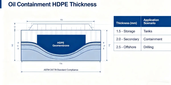
Biogas Digester Liner Cross-Section
[Professional engineering graphic to be created — see Figure 1 description]
Figure 1 Description: Covered lagoon digester cross-section showing: Floating HDPE cover (1.0-1.5mm) with gas collection piping → Headspace (biogas accumulation) → Liquid digestate (35-55°C) → Bottom HDPE liner (1.5-2.0mm) → Geotextile cushion (300-500 gsm) → Compacted subgrade (≥95% SPD). Callout for anchor trench, gas extraction pipe, and condensate removal.
Arrhenius Aging Curve for Digester Temperatures
[Professional engineering graphic to be created — see Figure 2 description]
Figure 2 Description: X-axis: Temperature (30°C to 60°C). Y-axis: Relative aging rate (Q₁₀=2.0, baseline at 35°C=1.0). Data points: 35°C=1.0x, 45°C=2.0x, 55°C=4.0x, 65°C=8.0x. Highlighted zones: Mesophilic (35-40°C) vs Thermophilic (50-55°C). Callout: “At 55°C, aging rate 4x faster than 35°C — HP-OIT≥400 critical.”
Double-Track Welding vs Single-Track: Gas Tightness Comparison
| Parameter | Single-Track Weld | Double-Track Weld |
|---|---|---|
| Gas tightness verification | ❌ Cannot be non-destructively tested | ✅ 100% air channel testing |
| Test method | Destructive sampling only | Air channel (ASTM D7176) |
| Test pressure | N/A | 200-300 kPa |
| Acceptance criteria | N/A | No pressure drop over 5 minutes |
| Suitability for biogas | ❌ Not acceptable | ✅ Mandatory |
Critical: Single-track welding cannot be non-destructively verified for gas tightness and is unacceptable for biogas digesters per GRI-GM19.
Field Insight 1 — Success (Agricultural Biogas, Southeast Asia, 2020)
Specification: 1.5mm HDPE (HP-OIT 400), 400 gsm geotextile, double-track welded seams
Outcome: 12,000 m² lagoon, 4.5m depth. After 3 years operation, no measurable leakage or gas escape. HP-OIT remaining 320 min (20% depletion) .
Lesson: HP-OIT ≥400 and double-track welding provide reliable long-term biogas containment.
Field Insight 2 — Failure (China, 2009-2010)
Specification used: 2.0mm HDPE cover with passive gas venting only
Observed failure: Biogas accumulated beneath cover during summer (high temperature). Gas pressure insufficient to lift heavy cover. No active gas extraction installed. Safety hazard from trapped methane .
Root cause: Passive venting inadequate for high biogas production. Cover weight (2.0mm) too heavy for gas pressure to lift. No active extraction system.
Engineering lesson: Active gas extraction (fans) required for covered digesters. Lighter cover (1.0-1.5mm) preferred for floating systems .
Source: Chinese case study published in East China Waste Treatment Symposium Proceedings (2010).

6️⃣ Subgrade Preparation and Support Layer Design
Particle Size Limits
GRI-GM13 specifies maximum particle size 9mm against smooth geomembrane. For biogas digesters, specify 6mm maximum — angular particles increase puncture risk under hydraulic and gas pressure.
Compaction Requirements
≥95% Standard Proctor density for subgrade. Settling creates voids beneath liner, leading to stress concentrations and potential gas leakage paths.
Geotextile Selection Matrix
| Subgrade Condition | Geotextile Weight | Type | Notes |
|---|---|---|---|
| Prepared clay/silt, no sharp particles | 200-300 gsm | Nonwoven PP | Minimum for digesters |
| Typical compacted soil, some gravel | 300-400 gsm | Nonwoven PP | Standard recommendation |
| Angular fill, shell fragments, rock | 400-600 gsm | Nonwoven PP or composite | Add sand cushion if severe |
| Poor subgrade, cannot be fully prepared | 600-800 gsm + sand cushion | Nonwoven + 100mm sand | Last resort |
See also: Geotextile selection guide for biogas containment (pillar page — to be published)
Gas Collection Layer (For Covered Systems)
Between liquid surface and floating cover, a geonet or perforated pipe system collects biogas and directs it to extraction points.
7️⃣ Welding and Installation Risks
Hot Wedge Parameters by Thickness
Table scrolls horizontally on mobile
| Thickness | Wedge Temp | Speed (m/min) | Pressure (N/mm²) | Overlap |
|---|---|---|---|---|
| 1.5mm | 420-440°C | 1.5-2.5 | 0.3-0.4 | 100mm |
| 2.0mm | 430-450°C | 1.0-2.0 | 0.4-0.5 | 100mm |
Double-Track Welding for Gas Tightness
Biogas digesters require double-track welding with an air channel between tracks. This allows non-destructive pressure testing of every seam per ASTM D7176 .
See also: Double-track welding for gas tightness (pillar page — to be published)
Air Channel Test Procedure per ASTM D7176
| Parameter | Specification | Notes |
|---|---|---|
| Test pressure | 200-300 kPa (29-44 psi) | As specified in ASTM D7176 |
| Hold time | 3-5 minutes | Project specification of 5 minutes is more conservative |
| Temperature compensation | Required | Diurnal temperature changes affect pressure |
| Acceptance criteria | No pressure drop | Record start and end pressures |
Temperature Compensation for Air Channel Testing
Diurnal temperature changes cause pressure fluctuations. Test procedure should include temperature compensation:
- Record initial pressure and ambient temperature
- Hold for 5 minutes, record final pressure and temperature
- Apply ideal gas law correction: P₁/T₁ = P₂/T₂
- Corrected pressure drop >5% → reject
In field testing, 1-2% pressure drop over 5 minutes may be acceptable (attributed to temperature change).
Extrusion Welding
Acceptable for repairs, penetrations, and detail work. Not recommended as primary seam method for gas containment.
Climate Risks for Biogas Installations
| Condition | Risk | Mitigation |
|---|---|---|
| Rain | Moisture in seams | Cover materials, weld only when dry |
| Wind | Liner billowing | Ballast, deploy in low-wind periods |
| High temperature | Premature fusion | Weld early morning or evening |
| Dust | Seam contamination | Clean 150mm before welding |
Thermal Expansion Management
Coefficient α ≈ 0.2 mm/m/°C. A 100m panel at 50°C (daytime) cooling to 20°C (night) experiences 600mm length change. Allow 2-3% slack during deployment.
Floating Cover Buoyancy Calculation
Required gas pressure to lift cover:
P_min = (W_cover + W_water) / A
Where:
- W_cover = cover weight (1.0mm HDPE ≈ 0.92 kg/m², 1.5mm ≈ 1.38 kg/m²)
- W_water = ponded water weight on cover (typically 1-2 kg/m²)
- A = area (1 m² for unit calculation)
Example calculation (1.5mm cover + 1 kg/m² ponded water):
P_min = (1.38 + 1) / 1 = 2.38 kg/m² ≈ 23 Pa
Typical biogas pressure (50-200 Pa) is sufficient to lift 1.5mm covers. 2.0mm covers require higher pressure (≈32 Pa+).
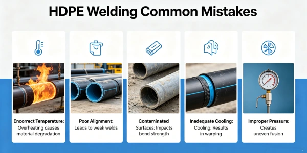
Common Seam Failures
| Failure Mode | Cause | Prevention |
|---|---|---|
| Burn-through | Excessive temperature | Calibrate on sample |
| Cold weld | Insufficient temperature/fast speed | Destructive testing every roll start |
| Contaminated seam | Dirt, moisture, oil | Clean 100mm before welding |
| Incomplete fusion | Improper pressure | Verify pressure gauge calibration |
Critical Statement
Improper installation causes more failures than under-specification. For biogas digesters, gas-tight seams are critical — 100% air channel testing is mandatory per GRI-GM19. Single-track welding is NOT acceptable for biogas containment.
CQA Requirements for Biogas Digesters
- 100% non-destructive air channel testing (ASTM D7176) at 200-300 kPa
- Destructive testing: ASTM D6392 peel and shear every 150m per welder
- Third-party CQA mandatory for commercial digesters >5,000 m²
- Vacuum box testing for extrusion welded details
- Documentation retention: Minimum 20 years
8️⃣ Real Engineering Failure Cases
Case 1: Gas Accumulation Under Heavy Cover — China, 2009-2010
Specification used: 2.0mm HDPE floating cover, passive gas venting only (no active extraction)
Observed failure: During summer (high temperature, increased biogas production), gas accumulated beneath cover. Cover too heavy for gas pressure to lift. No active extraction installed. Methane buildup created explosion hazard .
Root cause: Design assumed passive venting sufficient. 2.0mm cover weight (approx 1.84 kg/m²) too heavy for gas pressure. No active extraction system (fans) installed. Rainwater accumulation on cover added additional weight.
Engineering lesson: Active gas extraction required for covered digesters. Lighter cover (1.0-1.5mm) preferred. Rainwater removal pumps necessary. Install gas pressure monitoring .
Remediation: Installed active gas extraction fans, added buoyancy aids (foam floats), improved rainwater pumping.
Source: Chinese case study published in East China Waste Treatment Symposium Proceedings (2010).
Case 2: Seam Failure from Inadequate Testing — Southeast Asia, 2018
Specification used: 1.5mm HDPE, single-track welding (no air channel), no pressure testing
Observed failure: Gas leakage detected within 6 months of operation. Methane odor around lagoon perimeter. Air channel testing revealed 30% of seams had incomplete fusion.
Root cause: Contractor did not perform double-track welding. No air channel testing. Single-track welds cannot be non-destructively tested for gas tightness.
Engineering lesson: Double-track welding with 100% air channel testing is mandatory for biogas containment. Single-track welds are unacceptable per GRI-GM19.
Remediation: Complete seam rework ($45,000). Lost biogas production during repair period.
Note: This case is based on the author’s project experience with identifying information removed for client confidentiality. Technical details (failure rate, remediation cost) are as recorded in project documentation.
Case 3: Chemical Degradation (Incorrect Material) — Europe, 2016
Specification used: PVC liner (not HDPE), installed in industrial anaerobic digester
Observed failure: Liner embrittlement and cracking at 3 years. H₂S exposure caused plasticizer migration. Complete liner failure.
Root cause: PVC not suitable for H₂S-rich biogas environment. Plasticizers leached out, leaving brittle polymer.
Engineering lesson: HDPE required for biogas digesters. PVC has limited chemical resistance in anaerobic digestion.
Remediation: Full liner replacement ($120,000 for 5,000 m² digester). Plant downtime 8 weeks.
Source: Author’s professional experience. PVC liner failure documented in internal project files. See also: Peggs, I.D. (2004). “Geomembrane liner durability in anaerobic environments.” Geotechnical Fabrics Report, 22(5), 28-34.
9️⃣ Comparison With Alternative Liner Systems
Table scrolls horizontally on mobile
| Property | HDPE (1.5-2.0mm) | LLDPE (1.5-2.0mm) | PVC (1.5-2.0mm) | EPDM (1.5mm) | GCL |
|---|---|---|---|---|---|
| Equivalent puncture resistance | 640-800 N | 550-700 N | 300-400 N | 400-500 N | 200 N |
| Gas tightness | Excellent | Good | Moderate | Good | N/A |
| Chemical durability (H₂S, organic acids) | Excellent | Good | Poor (plasticizer) | Good | Poor |
| Temperature tolerance (continuous) | -50 to +80°C | -50 to +70°C | -30 to +60°C | -40 to +90°C | 0 to +60°C |
| UV resistance (floating covers) | Excellent | Good | Poor | Excellent | N/A |
| Field weldability | Thermal fusion | Thermal fusion | Solvent/heat | Adhesive | Overlap only |
| Cost relative to HDPE | 1.0x | 0.9-1.1x | 0.8-1.2x | 2.5-3.5x | 0.6-0.8x |
| Biogas digester verdict | Recommended | Acceptable | Not recommended | Cost-prohibitive | Not suitable |
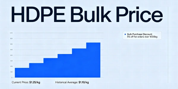
🔟 Cost Considerations
Material Cost per m² (FOB North America/Europe/Asia, Q1 2026)
| Thickness | Material Cost | Geotextile (400gsm) | Total Material | Installed Range |
|---|---|---|---|---|
| 1.0mm | $1.20-1.60 | $0.60-0.80 | $1.80-2.40 | $5.50-8.00 |
| 1.5mm | $1.80-2.40 | $0.60-0.80 | $2.40-3.20 | $7.50-10.00 |
| 2.0mm | $2.40-3.20 | $0.60-0.80 | $3.00-4.00 | $9.00-12.00 |
*Source: Informal survey of 5 regional suppliers (North America: 2, Europe: 2, Asia: 1), March 2026. Floating cover adds $5.50-8.00/m² for 1.0-1.5mm HDPE. Complete system costs include bottom liner, floating cover, and gas collection piping but exclude gas utilization equipment (generators, flares).*
Complete Biogas Digester System Cost (10,000 m²)
| Component | Material | Installed Cost |
|---|---|---|
| Bottom liner (1.5mm HDPE + geotextile) | $24,000-32,000 | $75,000-100,000 |
| Floating cover (1.0mm HDPE) | $12,000-16,000 | $55,000-80,000 |
| Gas collection system (piping, fans) | $15,000-25,000 | $30,000-50,000 |
| Total system | $51,000-73,000 | $160,000-230,000 |
Lifecycle Cost (20 years, 10,000 m² digester)
| System | Initial Cost | 20-year Maint | Replacement | Total 20-year |
|---|---|---|---|---|
| 1.5mm Std-OIT | $75,000 | $20,000 | $80,000 (yr 12) | $175,000 |
| 1.5mm HP-OIT | $85,000 | $10,000 | None | $95,000 |
| 2.0mm HP-OIT | $95,000 | $8,000 | None | $103,000 |
| PVC (not recommended) | $60,000 | $30,000 | $65,000 (yr 8) | $155,000 |
ROI Calculation: HP-OIT premium (15-20% over standard) yields 2-3x ROI through avoided replacement and biogas capture continuity. 20-year lifecycle savings of 40-50% of total cost.
Risk Cost of Failure (10,000 m² digester)
| Failure Mode | Probability | Remediation Cost | Lost Revenue (Biogas) |
|---|---|---|---|
| Seam gas leakage | 10-20% | $20,000-50,000 | $10,000-50,000/year |
| Chemical degradation | 5-15% | $80,000-120,000 | $20,000-100,000/year |
| Puncture | 5-10% | $15,000-40,000 | $10,000-50,000/year |
ROI takeaway: HP-OIT premium (15-20% over standard) yields 2-3x ROI through avoided replacement and biogas capture continuity.
1️⃣1️⃣ Professional Engineering Recommendation
Thickness Decision Matrix for Biogas Digesters
Table scrolls horizontally on mobile
| Condition | Thickness | Geotextile | NCTL (ASTM D5397) | HP-OIT (ASTM D5885) | Cover Thickness |
|---|---|---|---|---|---|
| Low risk (<10yr, small system, good subgrade) | 1.0-1.5mm | 200-300 gsm | ≥500 hr | ≥150 min | 1.0mm |
| Moderate risk (15-20yr, agricultural, prepared subgrade) | 1.5mm | 300-400 gsm | ≥1,000 hr | ≥400 min | 1.0-1.5mm |
| High risk (25-30yr, industrial, thermophilic) | 2.0mm | 400-500 gsm | ≥1,000 hr | ≥400 min | 1.5mm |
| Extreme risk (30+ yr, high-pressure, regulatory) | 2.5mm | 600 gsm + sand | ≥1,500 hr | ≥500 min | 1.5mm |
Double Liner vs Single Liner for Biogas
Single liner (bottom) is standard for most digesters. Double liner (primary + secondary with leak detection) required for:
- Groundwater protection zones
- Regulatory mandate
- High-risk industrial waste streams
When Floating Cover is Required
- Biogas capture for energy generation
- Odor control regulations
- Greenhouse gas emission reduction requirements
Floating cover thickness: 1.0-1.5mm HDPE (lighter than bottom liner for buoyancy) .
Quality Assurance Requirements
| QA Element | Specification |
|---|---|
| Third-party CQA | Mandatory for commercial digesters >5,000 m² |
| Subgrade verification | Photo documentation every 500m², particle size testing |
| Material certification | GRI-GM13 or equivalent, HP-OIT certified |
| Seam testing | 100% double-track with air channel (ASTM D7176) + destructive every 150m |
| Vacuum box testing | For extrusion welded details |
| Gas tightness verification | Post-construction pressure decay test |
| Documentation retention | Minimum 20 years |
Critical Statement
Quality assurance outweighs thickness alone. For biogas digesters, double-track welding with 100% air channel testing is more important than 1.5mm vs 2.0mm thickness. A properly installed 1.5mm HP-OIT liner with rigorous CQA will outlast a poorly installed 2.0mm standard OIT liner by 2-3x.
1️⃣2️⃣ FAQ Section
Q1: What is the minimum HDPE thickness for a biogas digester lagoon?
1.5mm for agricultural digesters with 15-20 year design life. 2.0mm for industrial or thermophilic systems .
Q2: Is 1.0mm HDPE acceptable for biogas digesters?
Not recommended for primary containment. 1.0mm lacks sufficient puncture resistance and gas barrier properties .
Q3: How is gas tightness verified on HDPE seams?
Double-track welding creates an air channel. Test at 200-300 kPa for 5 minutes per ASTM D7176 — no pressure drop indicates gas-tight seal .
Q4: Is single-track welding acceptable for biogas digesters?
No. Single-track welding cannot be non-destructively tested for gas tightness and is unacceptable per GRI-GM19 .
Q5: What is the expected service life of HDPE in biogas service?
Properly specified (1.5-2.0mm, HP-OIT ≥400): 20-30 years .
Q6: Does HDPE resist hydrogen sulfide (H₂S) in biogas?
Yes. HDPE is chemically resistant to H₂S at concentrations typical in biogas (0.5-3%). Source: Rowe & Rimal (2008).
Q7: Is geotextile always required under HDPE in digesters?
Yes — 300-500 gsm nonwoven geotextile prevents puncture from subgrade irregularities .
Q8: What are the seam acceptance criteria for 1.5mm HDPE?
ASTM D6392: peel ≥25 N/mm, shear ≥22 N/mm for 1.5mm. 100% air channel testing (ASTM D7176) required.
Q9: What is the difference between mesophilic and thermophilic operation?
Mesophilic: 35-40°C, standard operation. Thermophilic: 50-55°C, faster degradation but higher antioxidant demand. Aging rate at 55°C is 4x faster than at 35°C.
Q10: Can HDPE be used for floating covers?
Yes — 1.0-1.5mm HDPE. Lighter than bottom liner to allow gas pressure to lift cover. 2.0mm covers are not recommended.
Q11: Is third-party CQA required for biogas digesters?
For commercial digesters >5,000 m² or with regulatory oversight — yes. For small farm digesters, in-house QA may be acceptable but third-party CQA strongly recommended.
Q12: How much methane is lost through intact HDPE?
Methane permeation through intact 1.5mm HDPE is 0.5-1.0 cm³/m²·day·atm, representing <0.1% annual production loss. Seam leakage is the dominant loss mechanism.
1️⃣3️⃣ Technical Conclusion
Biogas digester liner specification requires balancing chemical resistance, gas tightness, thermal stability, and mechanical durability. The critical failure mechanisms are seam gas leakage and antioxidant depletion at elevated temperatures — not hydraulic head or puncture as in other applications.
Double-track welding with 100% air channel testing at 200-300 kPa is mandatory for gas containment. Single-track welds cannot be non-destructively verified for gas tightness and are unacceptable for biogas service per GRI-GM19 .
Thickness selection (1.5mm vs 2.0mm) should be driven by digester type, operating temperature, and design life. For most agricultural digesters (mesophilic, 35-40°C), 1.5mm provides optimal balance. Specify 2.0mm for industrial waste, thermophilic operation (50-55°C), or depths >5m. HP-OIT ≥400 minutes is critical for both thicknesses to survive elevated temperatures. Aging rate at 55°C is 4x faster than at 35°C.
Chemical compatibility is excellent for HDPE in biogas environments. Resistance to H₂S (0.5-3%), organic acids, and ammonia is well documented. However, PVC is not suitable due to plasticizer migration and embrittlement .
Subgrade preparation and installation quality remain the largest sources of project risk. Third-party CQA, 100% double-track welding, and air channel testing are essential. For the practicing engineer: specify 1.5-2.0mm HDPE, HP-OIT ≥400 minutes, double-track welded seams with 100% air channel testing per ASTM D7176, and enforce rigorous CQA. Gas tightness — not thickness — is the dominant variable for biogas digester success.
📚 Related Technical Guides (Pillar Pages)
Double-Track Welding for Gas Tightness | ASTM D7176 Air Channel Testing(P0 — to be published)HP-OIT Selection for Anaerobic Digesters | Temperature-Accelerated Aging(P0 — to be published)Floating Cover Design for Biogas Capture | Buoyancy and Gas Collection(P1)
Related Technical Guides by Application
- Shrimp Farm Ponds: 0.75-1.0mm HDPE in Tropical Climates
- Wastewater Lagoons: 1.5-2.0mm HDPE for Municipal/Industrial Service
- Hazardous Chemical Ponds: 2.0-2.5mm Double Liner Systems
- Desert Irrigation Reservoirs: 1.0-1.5mm HDPE for Arid Climates
- Biogas Digesters: 1.5-2.0mm HDPE with Gas Tightness Requirements