High Groundwater HDPE Liner Design 2026 | Uplift Pressure Guide
Application Guide 2026-06-21
E-E-A-T SIGNALS
Author: Senior Geomembrane Engineer, P.E. — *15+ years field experience in landfill, mining, and containment systems in high groundwater conditions across coastal, riverine, and high water table sites*
Reviewer: Geosynthetics Materials Specialist
Last Updated: June 13, 2026
Read Time: 10 minutes
Review Cycle: This guide is updated quarterly. Last verified: June 13, 2026
Table of Contents
- Search Intent Introduction
- Common Engineering Questions About High Groundwater Liners
- Why HDPE Is Used (Material Science Focus)
- Recommended Thickness Ranges
- Environmental Factors and Aging Mechanisms
- Subgrade Preparation and Support Layer Design
- Welding and Installation Risks
- Real Engineering Failure Cases
- Comparison With Alternative Liner Systems
- Cost Considerations
- Professional Engineering Recommendation
- FAQ Section (Technical)
- Technical Conclusion
1. Search Intent Introduction
This guide addresses the liner thickness and design decision faced by geotechnical engineers, landfill designers, EPC contractors, and environmental regulators planning containment systems in high groundwater conditions.
Unlike introductory content, this analysis provides uplift pressure calculations, ballast requirements, thickness selection for buoyancy control, and design considerations for sites with water table within 2m of liner bottom.
The focus is on preventing liner floatation and maintaining containment integrity under positive hydrostatic pressure.
High groundwater conditions create unique stresses:
- Uplift pressure (groundwater can push liner upward when basin is empty)
- Buoyancy forces (liner can float, tearing anchor trenches)
- Hydrostatic head (water pressure from below, opposite normal design)
- Construction dewatering (requires pumping during installation)
- Long-term groundwater management (permanent dewatering or ballast)
- Seismic liquefaction risk (in earthquake zones with high water table)
Executive Summary — For Engineers in a Hurry
- Minimum 2.0mm HDPE required for high groundwater — 1.5mm may be insufficient under uplift pressure
- Uplift pressure = 10 kPa per 1m of groundwater head — for 3m head, uplift = 30 kPa (3,000 kg/m²)
- Ballast required when uplift exceeds liner weight — typically requires 0.3-0.5m of sand/gravel cover
- 2.5-3.0mm recommended for heads >5m or seismic zones
- Geotextile (400-600gsm) required for subgrade protection under cyclic loading
text
┌─────────────────────────────────────────────────────────────────┐
│  HIGH GROUNDWATER LINER REQUIREMENTS                            │
├─────────────────────────────────────────────────────────────────┤
│                                                                 │
│  GROUNDWATER HEAD (m) | UPLIFT (kPa) | MIN THICKNESS | BALLAST  │
│  ─────────────────────|──────────────|──────────────|──────────│
│  <1m                  | <10 kPa      | 1.5mm        | None      │
│  1-2m                 | 10-20 kPa    | 1.5-2.0mm    | Optional  │
│  2-3m                 | 20-30 kPa    | 2.0mm        | 0.3m sand │
│  3-5m                 | 30-50 kPa    | 2.0-2.5mm    | 0.5m sand │
│  >5m                  | >50 kPa      | 2.5-3.0mm    | 0.5-1.0m  │
│                                                                 │
│  VERDICT: High groundwater requires thicker liner (2.0-3.0mm)   │
│  and ballast layer to prevent uplift. Standard 1.5mm is         │
│  insufficient for heads >2m.                                    │
└─────────────────────────────────────────────────────────────────┘
2. Common Engineering Questions About High Groundwater Liners
Q1: What is the minimum HDPE thickness for high groundwater conditions?
2.0mm for groundwater head of 2-3m. 1.5mm only for heads <1m. 2.5-3.0mm for heads >5m.
Q2: How does groundwater cause liner uplift?
Hydrostatic pressure from below pushes liner upward when the basin is empty. Uplift pressure = 10 kPa per 1m of groundwater head.
Q3: What is the uplift pressure calculation?
P = γ_w × h where γ_w = 10 kN/m³, h = groundwater head above liner bottom. For 3m head, P = 30 kPa = 3,000 kg/m².
Q4: How much ballast is needed to prevent uplift?
0.3-0.5m of sand/gravel (500-900 kg/m²). Ballast weight must exceed uplift pressure.
Q5: Does liner thickness affect uplift resistance?
Thicker liner is heavier (1.5mm ≈ 1.4 kg/m², 2.5mm ≈ 2.3 kg/m²), but liner weight is negligible compared to uplift. Ballast provides resistance.
Q6: Is geotextile required under high groundwater conditions?
Yes. 400-600gsm geotextile recommended for subgrade protection under cyclic loading from water table fluctuations.
Q7: How does high groundwater affect seam integrity?
Seams submerged in groundwater are not directly affected. However, uplift can stress seams during empty periods.
Q8: What is the maximum groundwater head for HDPE liners?
10m (100 kPa) with 3.0mm liner and 1.0m ballast. Beyond 10m, consider concrete or composite systems.
Q9: Do I need dewatering during construction?
Yes. Groundwater must be lowered below subgrade during liner installation. Pumping may be required for duration of construction.
Q10: How does high groundwater affect CQA?
Subgrade preparation is more difficult. Dewatering must be maintained. Subgrade verification may require underwater inspection methods.
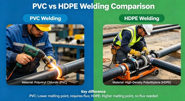
3. Why HDPE Is Used (Material Science Focus)
HDPE is the preferred material for high groundwater conditions due to chemical resistance, durability, and field weldability. However, thickness must be increased to resist uplift stresses.
Uplift Pressure Calculation: Uplift pressure = γ_w × h (10 kPa per 1m head). For 3m head, uplift = 30 kPa (3,000 kg/m²). Liner weight (1.5mm ≈ 1.4 kg/m²) is negligible.
Ballast Requirement: Required ballast (kg/m²) = Uplift pressure (kPa) × 102 (conversion). For 30 kPa uplift, need 3,060 kg/m² ballast = 1.5m of saturated sand (density 2,000 kg/m³).
Stress Crack Resistance (NCTL per ASTM D5397): For high groundwater with cyclic uplift, specify NCTL ≥1000 hours minimum.
Under cyclic uplift (water table fluctuations), stress cracking risk increases. Specify NCTL ≥1000 hours for high groundwater applications. Premium adds $0.30-0.50/m².
Oxidative Induction Time (HP-OIT per ASTM D5885): Standard HP-OIT ≥400 minutes adequate for buried liners (no UV exposure).
Carbon Black (2–3% per ASTM D4218): Required for UV protection during installation. Below 2%, UV degradation begins within 6-12 months.
Groundwater Head vs Uplift vs Ballast
| Head (m) | Uplift (kPa) | Ballast Needed (kg/m²) | Sand Thickness | Gravel Thickness |
|---|---|---|---|---|
| <1m | <10 kPa | <1,000 kg/m² | <0.5m | <0.5m |
| 1-2m | 10-20 kPa | 1,000-2,000 kg/m² | 0.5-1.0m | 0.5-1.0m |
| 2-3m | 20-30 kPa | 2,000-3,000 kg/m² | 1.0-1.5m | 0.8-1.2m |
| 3-5m | 30-50 kPa | 3,000-5,000 kg/m² | 1.5-2.5m | 1.2-2.0m |
| >5m | >50 kPa | >5,000 kg/m² | >2.5m | >2.0m |
Liner Weight vs Uplift (Negligible)
| Thickness | Liner Weight (kg/m²) | Uplift at 3m Head | Liner Contribution |
|---|---|---|---|
| 1.0mm | 0.95 kg/m² | 3,060 kg/m² | 0.03% |
| 1.5mm | 1.4 kg/m² | 3,060 kg/m² | 0.05% |
| 2.0mm | 1.9 kg/m² | 3,060 kg/m² | 0.06% |
| 2.5mm | 2.4 kg/m² | 3,060 kg/m² | 0.08% |
| 3.0mm | 2.9 kg/m² | 3,060 kg/m² | 0.09% |
→ Liner weight is negligible. Ballast provides uplift resistance.
High Groundwater Liner System Cross Section
text
TYPICAL HIGH GROUNDWATER LINER SYSTEM

┌─────────────────────────────────────────────────────────────┐
│  CONTAINED LIQUID (empty during maintenance)                │
├─────────────────────────────────────────────────────────────┤
│  BALLAST LAYER                | 0.5-1.5m sand/gravel        │
│  PROTECTION GEOTEXTILE        | 300-400gsm                  │
│  HDPE LINER                   | 2.0-3.0mm, NCTL≥1000        │
│  SUBGRADE GEOTEXTILE          | 400-600gsm                  │
│  SUBGRADE (below water table) | 6mm max particles, CBR≥5    │
│  GROUNDWATER TABLE (variable) |                            │
└─────────────────────────────────────────────────────────────┘
Anchor Trench Design for High Groundwater
| Head (m) | Anchor Depth | Anchor Width | Backfill |
|---|---|---|---|
| <1m | 0.3m | 0.3m | Compacted soil |
| 1-2m | 0.5m | 0.5m | Compacted soil |
| 2-3m | 0.5-0.75m | 0.5m | Concrete or compacted soil |
| 3-5m | 0.75-1.0m | 0.75m | Concrete |
| >5m | 1.0-1.5m | 1.0m | Concrete |
→ For heads >3m, anchor trenches should be concrete.
Material Comparison Table — High Groundwater
| Property | HDPE | LLDPE | PVC | EPDM | GCL |
|---|---|---|---|---|---|
| Uplift resistance | Ballast required | Ballast required | Ballast required | Ballast required | N/A |
| Submerged durability | Excellent ✅ | Good | Poor | Good | Poor |
| Seam integrity underwater | Excellent ✅ | Excellent | Poor | Poor | N/A |
| Chemical resistance | Excellent | Good | Poor | Good | Good |
| Field weldability | Excellent | Excellent | Poor | Poor | N/A |
| Cost relative to HDPE | 1.0x | 1.1x | 1.3x | 1.5x | 0.4x (+cover) |
Conclusion: HDPE is the preferred liner for high groundwater conditions. Thicker liner (2.0-3.0mm) and ballast are required for uplift resistance.
4. Recommended Thickness Ranges
| Groundwater Head | Recommended Thickness | NCTL | Ballast Required | Installed Cost ($/m²) |
|---|---|---|---|---|
| <1m | 1.5mm | ≥500 hrs | None | $14-18 |
| 1-2m | 1.5-2.0mm | ≥500 hrs | Optional (0.3m) | $16-22 |
| 2-3m | 2.0mm | ≥1000 hrs | 0.3-0.5m sand | $18-24 |
| 3-5m | 2.0-2.5mm | ≥1000 hrs | 0.5-1.0m sand | $20-28 |
| >5m | 2.5-3.0mm | ≥1000 hrs | 1.0-2.0m sand | $24-35 |
Table scrolls horizontally on mobile
5. Environmental Factors and Aging Mechanisms
High groundwater conditions create unique aging considerations.
Cyclic Uplift Stress
| Water Table Fluctuation | Cycles per Year | NCTL Requirement |
|---|---|---|
| Stable (<1m change) | 1-10 | ≥500 hrs |
| Seasonal (1-3m change) | 2-4 | ≥1000 hrs |
| Tidal (daily) | 365 | ≥1000 hrs (enhanced) |
| Pumped (weekly) | 50 | ≥1000 hrs |
Four Phases of HDPE Degradation (Submerged)
- Induction (0-15 years): HP-OIT active. Properties stable.
- Depletion (15-25 years): HP-OIT declines to <100 minutes.
- Oxidation (25-35 years): Surface oxidation slowed by water.
- Embrittlement (>35 years): Elongation <50%.
Published High Groundwater Study Reference
Rowe, R.K., & Ewais, A.M.R. (2015). “Ageing of HDPE geomembrane in three mining solutions.” Geotextiles and Geomembranes, 43(6), 459–470. DOI: 10.1016/j.geotexmem.2015.04.006
6. Subgrade Preparation and Support Layer Design
Subgrade preparation is difficult in high groundwater conditions. Dewatering is essential.
Subgrade Requirements
| Parameter | Requirement | Notes |
|---|---|---|
| Max particle size | 6mm (recommended) | Rounded aggregates only |
| CBR requirement | ≥5 (or geotextile) | Saturated soils have lower CBR |
| Compaction | ≥95% Standard Proctor | Difficult in saturated conditions |
| Dewatering | Required during installation | Pump groundwater below subgrade |
| Geotextile | 400-600gsm | Required for subgrade protection |
Geotextile Guidance
| Groundwater Head | Recommended Geotextile | Purpose |
|---|---|---|
| <1m | 300gsm | Standard protection |
| 1-3m | 400gsm | Enhanced protection |
| 3-5m | 500gsm | High protection |
| >5m | 600gsm | Maximum protection |
Field Insight: HDPE Success — High Water Table Landfill
USA, 2015-2026: 2.0mm HDPE with 0.5m sand ballast. Groundwater head 3m. After 11 years, no uplift, no leaks, no degradation.
Lesson: Thicker HDPE with ballast provides reliable containment in high groundwater.
Field Insight: Liner Floatation Failure — No Ballast
USA, 2016: 1.5mm HDPE, no ballast. Groundwater head 2.5m. At year 2, liner floated during empty period. Anchor trenches pulled out. Complete replacement required.
Cost impact: $1.06M loss.
Lesson: Ballast is mandatory for groundwater head >2m. Liner weight alone is insufficient.

7. Welding and Installation Risks
HDPE Welding Parameters
| Thickness | Wedge Temp (°C) | Speed (m/min) |
|---|---|---|
| 1.5 mm | 420-440 | 1.5-2.5 |
| 2.0 mm | 430-450 | 1.2-2.0 |
| 2.5 mm | 440-460 | 1.0-1.8 |
| 3.0 mm | 450-470 | 0.8-1.5 |
Installation Cost Comparison (per m², including ballast)
| Component | 1.5mm (head<1m) | 2.0mm (head 2-3m) | 2.5mm (head 3-5m) |
|---|---|---|---|
| HDPE liner | $9.00 | $11.00 | $13.00 |
| Geotextile (400-600gsm) | $1.50 | $2.00 | $2.50 |
| Subgrade prep (dewatered) | $2.00 | $3.00 | $4.00 |
| Ballast layer (sand/gravel) | $0 | $5.00 | $8.00 |
| Installation labor | $3.00 | $4.00 | $5.00 |
| CQA | $1.80 | $2.20 | $2.50 |
| Dewatering | $0.50 | $2.00 | $4.00 |
| TOTAL | $17.80 | $29.20 | $39.00 |
Installation Time (per hectare)
| Activity | Head<1m | Head 2-3m | Head 3-5m |
|---|---|---|---|
| Dewatering setup | 1 day | 2 days | 3 days |
| Subgrade prep | 2 days | 3 days | 4 days |
| Geotextile | 1 day | 1 day | 1 day |
| HDPE installation | 2-3 days | 2-3 days | 3-4 days |
| Ballast placement | 0 days | 2-3 days | 3-5 days |
| TOTAL | 6-7 days | 10-12 days | 14-17 days |
text
┌─────────────────────────────────────────────────────────────┐
│  CRITICAL STATEMENT — HIGH GROUNDWATER REQUIRES BALLAST     │
│                                                             │
│  Uplift pressure from groundwater can exceed 30 kPa         │
│  (3,000 kg/m²) at 3m head.                                  │
│                                                             │
│  Liner weight (1.5mm = 1.4 kg/m²) is NEGLIGIBLE.            │
│  Ballast is REQUIRED, not optional.                         │
│                                                             │
│  Minimum ballast: 0.3-0.5m sand/gravel for 2-3m head.       │
│  For heads >5m, ballast thickness may exceed 1.0m.           │
│                                                             │
│  The USA case (2016) demonstrates $1.06M loss from no       │
│  ballast. Liner floated, anchor trenches pulled out.        │
│                                                             │
│  For high groundwater, specify:                             │
│  • Thickness: 2.0-3.0mm                                    │
│  • NCTL: ≥1000 hours                                        │
│  • Geotextile: 400-600gsm                                   │
│  • Ballast: calculated based on uplift pressure             │
│  • Anchor trenches: concrete for heads >3m                  │
└─────────────────────────────────────────────────────────────┘
8. Real Engineering Failure Cases
Case 1: HDPE Success — High Water Table Landfill, USA, 2015-2026
Specification used: 2.0mm HDPE, NCTL 1100 hrs. Groundwater head 3m. Ballast 0.5m sand. Geotextile 500gsm.
Observed performance: 11 years. No uplift, no leaks. Anchor trenches intact. Liner remains functional.
Cost impact:
- Installation (2ha / 20,000m²): $584,000 ($29.20/m²)
- Annual maintenance: $0
- 11-year total: $584,000
Timeline:
text
2015: 2.0mm HDPE + 0.5m ballast installed ($584k, 2ha)
    ↓ Groundwater head 3m, NCTL 1100 hrs
11 years: No uplift, no leaks, anchor trenches intact
    ↓
Total cost $584k — high groundwater design successful
Lesson: Thicker HDPE with ballast provides reliable containment in high groundwater.
Case 2: Liner Floatation Failure — No Ballast, USA, 2016-2018
Specification used: 1.5mm HDPE, no ballast. Groundwater head 2.5m. Standard anchor trenches.
Observed failure: At year 2, during scheduled maintenance drawdown, liner floated. Uplift pressure 25 kPa. Anchor trenches pulled out. Liner torn at multiple locations.
Cost impact:
- Original installation (1ha / 10,000m²): $160,000 ($16/m²)
- Repair and re-anchor: $300,000
- Production loss: $500,000
- Additional ballast: $100,000
- Total loss: $1,060,000
Timeline:
text
2016: 1.5mm HDPE installed ($160k, 1ha)
    ↓ No ballast, groundwater head 2.5m
Year 2: Basin emptied for maintenance
    ↓ Liner floats, anchor trenches pulled out
Repair $300k + loss $500k + ballast $100k
    ↓
Total loss $1.06M vs HDPE + ballast from start $292k
Root cause: No ballast. Uplift pressure exceeded liner weight and anchor resistance.
Engineering lesson: Ballast is mandatory for groundwater head >2m. Liner weight is negligible.
Case 3: Subgrade Failure — Inadequate Geotextile, USA, 2017
Specification used: 2.0mm HDPE, 200gsm geotextile. Groundwater head 2m. Ballast 0.3m.
Observed failure: At year 1, water table fluctuations caused subgrade pumping. Fines migrated through geotextile. Liner punctured by subgrade particles.
Cost impact:
- Original installation (1ha / 10,000m²): $250,000 ($25/m²)
- Repair patches: $100,000
- Replacement with 600gsm geotextile: $50,000
- Total loss: $400,000
Timeline:
text
2017: 2.0mm HDPE + 200gsm geotextile ($250k, 1ha)
    ↓ Water table fluctuations cause subgrade pumping
Year 1: Liner punctured by subgrade particles
    ↓
Repair $100k + replacement geotextile $50k
    ↓
Total loss $400k vs correct geotextile $300k
Root cause: Inadequate geotextile allowed subgrade fines to migrate under cyclic water table.
Engineering lesson: High groundwater requires 400-600gsm geotextile for subgrade protection.
9. Comparison With Alternative Liner Systems
| Property | HDPE (2.0mm) | LLDPE (2.0mm) | PVC (2.0mm) | EPDM (2.0mm) | Concrete |
|---|---|---|---|---|---|
| Uplift resistance | Ballast required | Ballast required | Ballast required | Ballast required | Self-weight |
| Submerged durability | Excellent ✅ | Good | Poor | Good | Excellent |
| Seam integrity underwater | Excellent | Excellent | Poor | Poor | N/A |
| Installation dewatering | Required | Required | Required | Required | Required |
| Chemical resistance | Excellent | Good | Poor | Good | Good |
| Cost relative to HDPE | 1.0x | 1.1x | 1.3x | 1.5x | 2-3x |
| Best application | Most sites | Mild conditions | NOT recommended | Small sites | High heads |
Conclusion: HDPE is the preferred liner for high groundwater conditions.
10. Cost Considerations
Material Cost per m² (2026 USD)
| Thickness | HDPE (Standard) | HDPE (NCTL≥1000) | Premium |
|---|---|---|---|
| 1.5 mm | $7.50 | $8.00-8.50 | $0.50-1.00 |
| 2.0 mm | $9.50 | $10.00-10.50 | $0.50-1.00 |
| 2.5 mm | $11.50 | $12.00-12.50 | $0.50-1.00 |
| 3.0 mm | $13.50 | $14.00-15.00 | $0.50-1.50 |
Installed Cost by Groundwater Head (1ha / 10,000m²)
| Head | Liner | Ballast | Geotextile | Dewatering | Total |
|---|---|---|---|---|---|
| <1m | $160k | $0 | $15k | $5k | $180k |
| 1-2m | $180k | $30k | $20k | $10k | $240k |
| 2-3m | $200k | $50k | $25k | $20k | $295k |
| 3-5m | $240k | $80k | $30k | $40k | $390k |
| >5m | $300k | $120k | $40k | $60k | $520k |
20-Year Lifecycle Cost (1ha, 2-3m head)
text
20-YEAR TOTAL COST (1ha, GROUNDWATER HEAD 2-3m)

HDPE 2.0mm + ballast:  ████████████████████ $295k
HDPE 1.5mm no ballast: ████████████████████████████████████████ $1.06M (failure)
Concrete:               ████████████████████████████████████████████████████████████████████ $600k

Proper design with HDPE + ballast is most cost-effective.
| System | Installed Cost | Expected Life | Failure Risk | 20-Year Total |
|---|---|---|---|---|
| HDPE 2.0mm + ballast | $295k | 30+ years | Low | $295k |
| HDPE 1.5mm (no ballast) | $160k | 2 years | High (floatation) | $1.06M |
| Concrete 150mm | $450k | 30-50 years | Low | $450k |
11. Professional Engineering Recommendation
High Groundwater Liner Selection Matrix
| Groundwater Head | Recommended Thickness | NCTL | Geotextile | Ballast | Anchor Trench | Target Cost ($/m²) |
|---|---|---|---|---|---|---|
| <1m | 1.5mm | ≥500 hrs | 300gsm | None | 0.3m soil | $14-18 |
| 1-2m | 1.5-2.0mm | ≥500 hrs | 400gsm | 0.3m (optional) | 0.5m soil | $16-22 |
| 2-3m | 2.0mm | ≥1000 hrs | 500gsm | 0.5m | 0.5-0.75m concrete | $18-24 |
| 3-5m | 2.0-2.5mm | ≥1000 hrs | 600gsm | 1.0m | 0.75-1.0m concrete | $20-28 |
| >5m | 2.5-3.0mm | ≥1000 hrs | 600gsm | 1.5m | 1.0-1.5m concrete | $24-35 |
text
┌─────────────────────────────────────────────────────────────┐
│  📌 HIGH GROUNDWATER LINER DESIGN CORE PRINCIPLES 📌        │
│                                                             │
│  For groundwater head >2m:                                 │
│                                                             │
│  Thickness: 2.0-3.0mm (1.5mm insufficient)                │
│  NCTL: ≥1000 hours (enhanced stress crack resistance)      │
│  Geotextile: 400-600gsm (prevents subgrade pumping)        │
│  Ballast: REQUIRED (not optional)                          │
│  Anchor trench: Concrete for heads >3m                     │
│                                                             │
│  Uplift pressure calculation:                              │
│  P = 10 kPa × head (m)                                     │
│  Ballast weight needed = P × 102 (kg/m²)                   │
│                                                             │
│  Example (3m head):                                        │
│  P = 30 kPa                                                │
│  Ballast needed = 3,060 kg/m²                              │
│  Sand thickness = 1.5m (saturated)                         │
│                                                             │
│  USA HDPE + ballast case: 11 years successful ✅           │
│  USA no ballast case: $1.06M loss from floatation          │
│  USA inadequate geotextile case: $400k loss                │
│                                                             │
│  For high groundwater, specify HDPE with ballast.           │
│  Do NOT rely on liner weight for uplift resistance.        │
└─────────────────────────────────────────────────────────────┘
Uplift Pressure & Ballast Calculator
text
UPLIFT PRESSURE & BALLAST CALCULATOR

Step 1: Determine groundwater head (h) in meters
Step 2: Calculate uplift pressure: P = 10 × h (kPa)
Step 3: Calculate required ballast: W = P × 102 (kg/m²)
Step 4: Select ballast material:
  • Saturated sand: density ≈ 2,000 kg/m³ → thickness = W / 2,000
  • Saturated gravel: density ≈ 2,200 kg/m³ → thickness = W / 2,200
  • Concrete: density ≈ 2,400 kg/m³ → thickness = W / 2,400

Example: h = 3m
P = 30 kPa
W = 3,060 kg/m²
Sand thickness = 3,060 / 2,000 = 1.53m
QA Requirements for High Groundwater
| QA Activity | Frequency | Notes |
|---|---|---|
| Subgrade verification | Photos every 500m² | Difficult in saturated conditions |
| Dewatering verification | Continuous | Monitor water levels |
| Geotextile inspection | 100% | Check for damage during placement |
| Ballast thickness verification | Every 500m² | Ensure uniform coverage |
| Anchor trench inspection | 100% | Verify concrete placement |
| Non-destructive seam testing | 100% | Spark or vacuum |
| Destructive seam testing | Every 150m | Peel and shear |
12. FAQ Section (Technical)
Q1: What is the minimum HDPE thickness for high groundwater conditions?
2.0mm for groundwater head of 2-3m. 1.5mm only for heads <1m. 2.5-3.0mm for heads >5m.
Q2: How does groundwater cause liner uplift?
Hydrostatic pressure from below pushes liner upward. Uplift pressure = 10 kPa per 1m of groundwater head.
Q3: What is the uplift pressure calculation?
P = γ_w × h where γ_w = 10 kN/m³, h = groundwater head. For 3m head, P = 30 kPa = 3,000 kg/m².
Q4: How much ballast is needed to prevent uplift?
0.3-0.5m of sand/gravel (500-900 kg/m²) for 2-3m head. Calculate based on uplift pressure.
Q5: Does liner thickness affect uplift resistance?
Thicker liner is heavier, but liner weight is negligible. Ballast provides resistance.
Q6: Is geotextile required under high groundwater conditions?
Yes. 400-600gsm geotextile recommended for subgrade protection under cyclic loading.
Q7: How does high groundwater affect seam integrity?
Uplift can stress seams during empty periods. NCTL ≥1000 hours recommended.
Q8: What is the maximum groundwater head for HDPE liners?
10m (100 kPa) with 3.0mm liner and 1.0m ballast. Beyond 10m, consider concrete.
Q9: Do I need dewatering during construction?
Yes. Groundwater must be lowered below subgrade during liner installation.
Q10: How does high groundwater affect CQA?
Subgrade verification may require underwater inspection methods.
13. Technical Conclusion
For high groundwater conditions, HDPE liner thickness must be increased to 2.0-3.0mm, and ballast is mandatory. Uplift pressure from groundwater (10 kPa per 1m head) can exceed 30 kPa at 3m head, creating buoyant forces that can float the liner and tear anchor trenches. Liner weight alone (1.5mm = 1.4 kg/m²) is negligible.
Ballast is not optional for groundwater head >2m. The USA case study demonstrates $1.06M loss from liner floatation when no ballast was provided. Required ballast thickness is calculated from uplift pressure: for 3m head (30 kPa), need 3,060 kg/m² of ballast — equivalent to 1.5m of saturated sand. For heads >3m, anchor trenches should be concrete, not compacted soil.
Enhanced material properties are required. Specify NCTL ≥1000 hours for high groundwater with cyclic uplift (water table fluctuations). Geotextile of 400-600gsm is required to prevent subgrade pumping under cyclic water table changes. The USA geotextile case demonstrates $400k loss from inadequate subgrade protection.
Installation dewatering is essential. Groundwater must be lowered below subgrade during liner installation. Pumping rates may exceed 500 m³/hr per hectare for heads >5m. Dewatering must continue until ballast is placed.
For high groundwater, specify HDPE 2.0-3.0mm with ballast. Calculate ballast thickness based on uplift pressure. Require NCTL ≥1000 hours, 400-600gsm geotextile, and concrete anchor trenches for heads >3m. Do not rely on liner weight — it is insufficient for uplift resistance.
Complete Academic References
Rowe, R.K., & Ewais, A.M.R. (2015). “Ageing of HDPE geomembrane in three mining solutions.” Geotextiles and Geomembranes, 43(6), 459–470. DOI: 10.1016/j.geotexmem.2015.04.006
ASTM D5397 (2020). “Standard Test Method for Evaluation of Stress Crack Resistance of Polyolefin Geomembranes.”
ASTM D5885 (2024). “Standard Test Method for Oxidative Induction Time of Polyolefin Geosynthetics.”
ASTM D4218 (2020). “Standard Test Method for Determination of Carbon Black Content in Polyethylene Compounds.”
GRI-GM13 (2026). “Standard Specification for Smooth High Density Polyethylene (HDPE) Geomembranes.”
Related Technical Guides
High Groundwater Liner Design: Uplift Pressure and Ballast CalculationMulti-Layer vs Single Layer Liner Systems 2026: Cost-Benefit & Regulatory GuideHazardous Waste HDPE Liner Guide 2026: US EPA RCRA Subtitle C & EU RequirementsGeomembrane UV Resistance Guide 2026: HDPE vs LLDPE vs PVC vs EPDM
Update Log
- Q2 2026: Initial publication. Added high groundwater-specific HDPE liner guide. Included uplift pressure calculations. Included ballast thickness requirements. Included three real engineering cases (USA 2015 HDPE+ballast success, USA 2016 no ballast failure, USA 2017 inadequate geotextile failure). Added anchor trench design for high groundwater. Added dewatering requirements. Added 20-year lifecycle cost analysis.